Home › Engine / Hybrid System › 2AZ-FE STARTING › SMART ENTRY AND START SYSTEM
RM24M0E _51 Engine / Hybrid System _059575 2AZ-FE STARTING _0292080 SMART ENTRY AND START SYSTEM C

2AZ-FE STARTING  SMART ENTRY AND START SYSTEM  B2272  Ignition 1 Monitor Malfunction  


DESCRIPTION

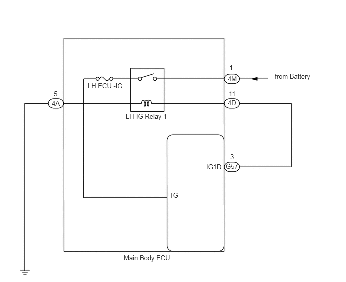
This DTC is output when a malfunction occurs in the IG1D output circuit, which is between the LH-IG relay 1 actuation circuit inside the main body ECU and the LH-IG relay 1.

DTC No. DTC Detection Condition Trouble Area
B2272 LH-IG relay 1 actuation circuit inside main body ECU or other related circuit is malfunctioning
·

Main body ECU

·

Wire harness


WIRING DIAGRAM

A137563E02
2.563,5.25 3.625,5.458 1.063,0.208 10 false Main Body ECU 2.604,2.323 3.573,2.531 0.969,0.208 10 false LH-IG Relay 1 1.813,1.688 2.615,1.958 0.802,0.271 10 false LH ECU -IG 4.271,3.365 4.677,3.635 0.406,0.271 10 false IG1D 3.542,3.958 3.865,4.188 0.323,0.229 10 false IG 5.688,1.49 6.542,1.771 0.854,0.281 10 false from Battery 1.073,2.052 1.302,2.25 0.229,0.198 10 false 4A 4.719,1.542 4.948,1.698 0.229,0.156 10 false 4M 4.719,2.042 4.948,2.208 0.229,0.167 10 false 4D 4.677,3.354 4.969,3.51 0.292,0.156 10 false G57 4.771,3.156 4.896,3.313 0.125,0.156 10 false 3 4.74,1.854 4.927,2.021 0.188,0.167 10 false 11 4.75,1.323 4.865,1.479 0.115,0.156 10 false 1 1.115,1.854 1.271,2.01 0.156,0.156 10 false 5

PROCEDURE

1.READ VALUE USING INTELLIGENT TESTER (LH-IG RELAY 1 MONITOR (OUTSIDE))
a.

Connect the intelligent tester to the DLC3.


b.

Turn the ignition switch on (IG) and turn the tester ON.


c.

Select the following menu items: Body / Main Body ECU / Data List / IG1 Relay Mon1.


d.

Read the display on the tester.

Main body ECU
Item Measurement Item / Display
(Range)
Normal Condition Diagnosis Note
IG1 Relay Mon1 LH-IG relay 1 outer relay monitor / ON or OFF ON: Ignition switch on (IG)
OFF: Ignition switch off
-

OK:

When the ignition switch is turned on (IG), ON is displayed on the tester.


OK

2.CHECK SWITCH CONDITION (ENGINE SWITCH)

NG

3.CHECK WIRE HARNESS (MAIN BODY ECU)
2.CHECK SWITCH CONDITION (ENGINE SWITCH)
a.

Ensure the electrical key is inside the cabin.


b.

Check that the power source mode changes as shown below each time the engine switch is pushed.

OK:

off → on (ACC) → on (IG) → off


OK

NORMAL

NG

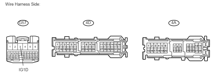
3.CHECK WIRE HARNESS (MAIN BODY ECU)
U188757E02
0.688,1.594 0.771,2.188 false 0.177,0.052 2.823,0.49 2.646,0.438 10 false Wire Harness Side: 0.625,0.667 1.083,0.875 0.458,0.208 10 false G57 0.625,2.24 1.104,2.438 0.479,0.198 10 false IG1D 2.854,0.667 3.313,0.875 0.458,0.208 10 false 4D 5.708,0.667 6.167,0.875 0.458,0.208 10 false 4A

a.

Disconnect the 4D, 4A and G57 main body ECU connectors.


b.

Measure the resistance of the wire harness side connectors.

Standard resistance:
Tester Connection Specified Condition
G57-3 (IG1D) - 4D-11 Below 1 Ω
G57-3 (IG1D) or 4D-11 - Body ground 10 kΩ or higher
4A-5 - Body ground Below 1 Ω


OK

REPLACE MAIN BODY ECU

NG

REPAIR OR REPLACE HARNESS OR CONNECTOR