2AZ-FE STARTING PUSH-BUTTON START B2278 Engine Switch Circuit Malfunction
DESCRIPTION
This DTC is output when 1) a malfunction is detected between the main body ECU and the engine switch; or 2) either of the switches inside the engine switch is malfunctioning.
| DTC No. | DTC Detection Condition | Trouble Area |
|---|---|---|
| B2278 | Communication is abnormal between main body ECU and engine switch or engine switch is defective | ·
Main body ECU ·
Engine switch ·
Wire harness |
WIRING DIAGRAM
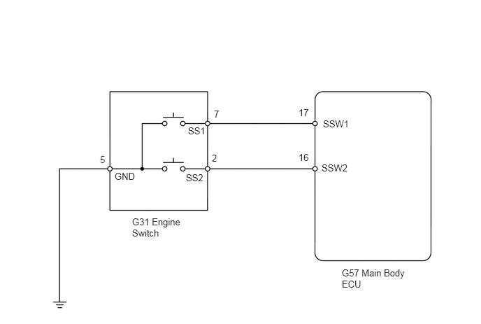
PROCEDURE
Connect the GTS to the DLC3.
Turn the engine switch on (IG) and turn the tester ON.
Select the following menu items: Body Electrical / Main Body ECU / Data List / St SW1 and St SW2.
Read the value displayed on the tester.
| Item | Measurement Item/Display (Range) | Normal Condition | Diagnostic Note |
|---|---|---|---|
| Start Switch1 | Start Switch 1 / ON or OFF | ON: Engine switch on (IG)
OFF: Engine switch off |
- |
| Start Switch2 | Start Switch 2 / ON or OFF | ON: Engine switch on (IG)
OFF: Engine switch off |
- |
- OK:
ON appears on the screen.
OK
NG
Ensure the electrical key is inside the cabin.
Check that the power source mode changes as shown below each time the engine switch is pushed.
- OK:
off → on (ACC) → on (IG) → off
OK
NG
(See pageEngine / Hybrid System>2AZ-FE STARTING>PUSH-BUTTON START>Power Source Mode does not Change)
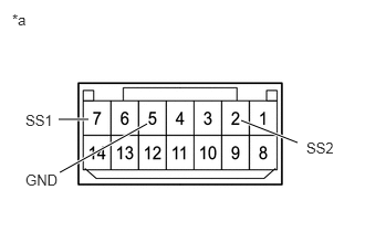
Remove the engine switch.
Measure the resistance of the switch.
- Standard resistance:
Tester Connection Switch Condition Specified Condition 7 (SS1) - 5 (GND) Pushed Below 1 Ω 2 (SS2) - 5 (GND) Pushed Below 1 Ω 7 (SS1) - 5 (GND) Not pushed 10 kΩ or higher 2 (SS2) - 5 (GND) Not pushed 10 kΩ or higher
Text in Illustration *a Component without harness connected
(Engine Switch)
OK
NG
Disconnect the G31 engine switch connector.
Disconnect the G57 main body ECU connector.
Measure the resistance of the wire harness side connectors.
- Standard resistance:
Tester Connection Specified Condition G31-7 (SS1) - G57-17 (SSW1) Below 1 Ω G31-2 (SS2) - G57-16 (SSW2) Below 1 Ω G31-5 (GND) - Body ground Below 1 Ω G31-7 (SS1) or G57-17 (SSW1) - Body ground 10 kΩ or higher G31-2 (SS2) or G57-16 (SSW2) - Body ground 10 kΩ or higher
OK
NG