U241E AUTOMATIC TRANSMISSION / TRANSAXLE AUTOMATIC TRANSAXLE UNIT DISASSEMBLY
PROCEDURE

 33403M
1.REMOVE SPEEDOMETER DRIVEN HOLE COVER SUB-ASSEMBLY
Remove the bolt and hole cover from the transaxle.
Remove the O-ring from the hole cover.
84540
2.REMOVE PARK/NEUTRAL POSITION SWITCH ASSEMBLY
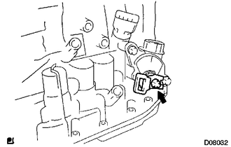
Remove the nut, washer and control shaft lever.
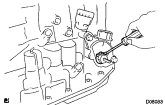
Using a screwdriver, unstake the lock plate and remove the lock nut and lock plate.
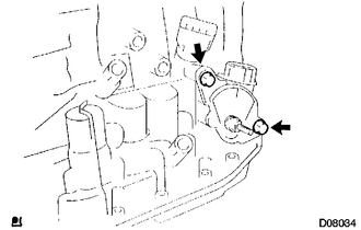
Remove the 2 bolts and pull out the park/neutral position switch.
35104V
3.REMOVE BREATHER PLUG HOSE
Remove the breather plug hose from the breather plug.
32921C
4.REMOVE OIL COOLER OUTLET TUBE UNION
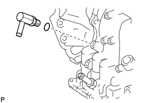
Remove the union.
Remove the O-ring from the union.
32921C
5.REMOVE OIL COOLER INLET TUBE UNION
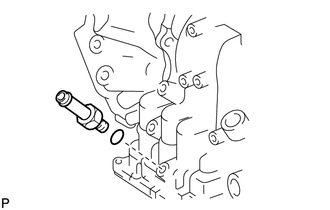
Remove the union.
Remove the O-ring from the union.
89413B
6.REMOVE SPEED SENSOR
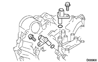
Remove the 2 bolts and 2 speed sensors from the transaxle.
Remove the 2 O-rings from the sensors.
33403M
7.REMOVE SPEEDOMETER DRIVEN HOLE COVER SUB-ASSEMBLY
Remove the bolt and the hole cover.
Remove the O-ring from the hole cover.
35104Q
8.REMOVE NO. 1 TRANSAXLE CASE PLUG
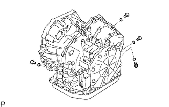
Remove the 4 plugs from the transaxle.
Remove the 4 O-rings from the 4 plugs.
30500
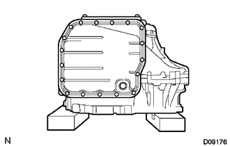
9.FIX AUTOMATIC TRANSAXLE ASSEMBLY
35106D
10.REMOVE AUTOMATIC TRANSAXLE OIL PAN SUB-ASSEMBLY
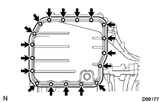
Remove the 18 bolts.
Remove the oil pan and 3 magnets.
Remove the gasket from the oil pan.
35106D
11.INSPECT AUTOMATIC TRANSAXLE OIL PAN SUB-ASSEMBLY
35330
12.REMOVE VALVE BODY OIL STRAINER ASSEMBLY
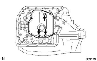
Remove the 3 bolts and oil strainer.
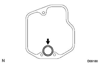
Remove the O-ring from the oil strainer.
82125J
13.REMOVE TRANSMISSION WIRE
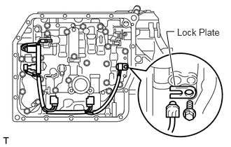
Remove the 5 connectors from the shift solenoid valves.
Remove the bolt, clamp and ATF temperature sensor.
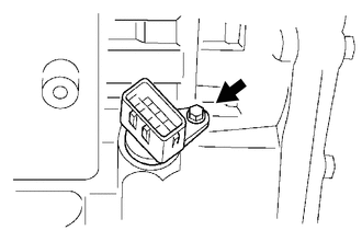
Remove the bolt and transaxle solenoid wire from the transaxle.
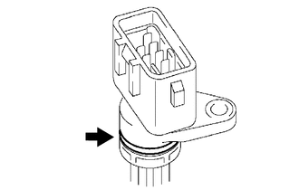
Remove the O-ring from the transaxle solenoid wire.
35410
14.REMOVE TRANSMISSION VALVE BODY ASSEMBLY
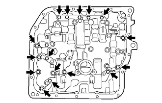
Support the valve body assembly and remove the 17 bolts and the valve body assembly.
35148
15.REMOVE NO. 1 GOVERNOR APPLY GASKET
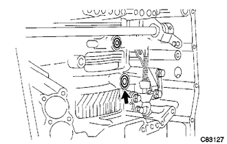
Remove the governor apply gasket from the transaxle.
35149B
16.REMOVE TRANSAXLE CASE 2ND BRAKE GASKET
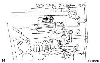
Remove the 2nd brake gasket from the transaxle.
35159
17.REMOVE BRAKE DRUM GASKET
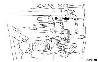
Remove the brake drum gasket from the transaxle.
35251
18.REMOVE CHECK BALL BODY
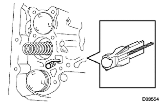
Remove the check ball body and spring from the transaxle.
35426D
19.REMOVE C-3 ACCUMULATOR PISTON
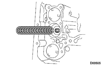
Remove the compression spring from the C-3 accumulator piston.
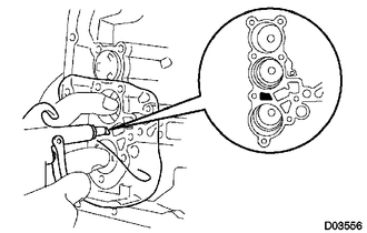
Apply compressed air (392 kPa, 4.0 kgf/cm2, 57 psi) to the oil hole and remove the C-3 accumulator piston.
- NOTICE:
- ·
Applying compressed air may cause the piston to jump out. When removing the piston, hold it with your hand using a waste cloth.
·Make sure not to spatter ATF when applying compressed air.
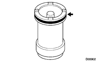
Remove the O-ring from the C-3 accumulator piston.
35424C
20.REMOVE C-1 ACCUMULATOR PISTON
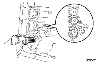
Apply compressed air (392 kPa, 4.0 kgf/cm2, 57 psi) to the oil hole and remove the C-1 accumulator piston and compression spring.
- NOTICE:
- ·
Applying compressed air may cause the piston to jump out. When removing the piston, hold it with your hand using a waste cloth.
·Make sure not to spatter ATF when applying compressed air.
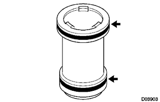
Remove the 2 O-rings from the C-1 accumulator piston.
35427K
21.REMOVE B-3 ACCUMULATOR PISTON
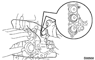
Apply compressed air (392 kPa, 4.0 kgf/cm2, 57 psi) to the oil hole and remove the B-3 accumulator piston and 2 compression springs.
- NOTICE:
- ·
Applying compressed air may cause the piston to jump out. When removing the piston, hold it with your hand using a waste cloth.
·Make sure not to spatter ATF when applying compressed air.
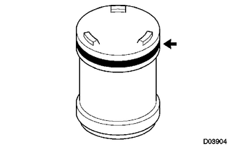
Remove the O-ring from the B-3 accumulator piston.
35409
22.REMOVE MANUAL DETENT SPRING SUB-ASSEMBLY
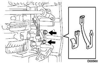
Remove the 2 bolts, manual detent spring and cover.
35595
23.REMOVE PARKING LOCK PAWL BRACKET
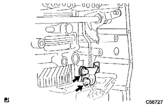
Remove the 2 bolts and parking lock pawl bracket.
35506J
24.REMOVE MANUAL VALVE LEVER SHAFT RETAINER SPRING
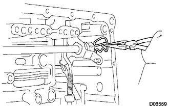
Using needle-nose pliers, remove the retainer spring.
35505
25.REMOVE MANUAL VALVE LEVER SUB-ASSEMBLY
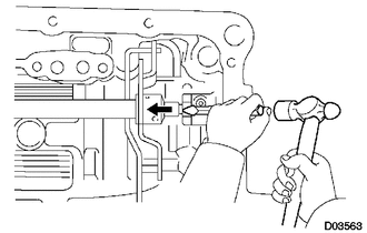
Using a chisel and hammer, unstake and remove the manual valve lever spacer.
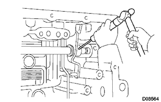
Using a pin punch and hammer, tap out the manual valve lever shaft spring pin.
- HINT:
-
Slowly drive out the pin so that it will not fall into the transaxle.
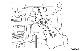
Remove the manual valve lever shaft and manual valve lever.
35501
26.REMOVE PARKING LOCK ROD SUB-ASSEMBLY
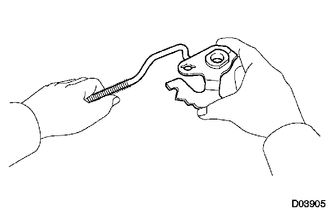
Remove the parking lock rod from the manual valve lever.
35506F
27.REMOVE MANUAL VALVE LEVER SHAFT OIL SEAL
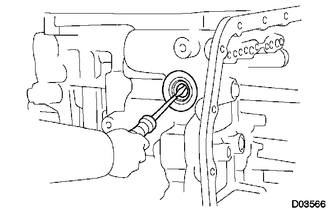
Using a screwdriver, pry out the oil seal from the transaxle.
28.INSPECT INPUT SHAFT END PLAY
35104Q
29.REMOVE NO. 1 TRANSAXLE CASE PLUG
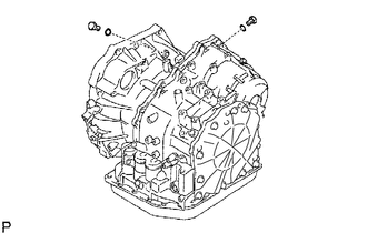
Remove the 2 plugs.
Remove the 2 O-rings from the plug.
35111C
30.REMOVE TRANSAXLE HOUSING
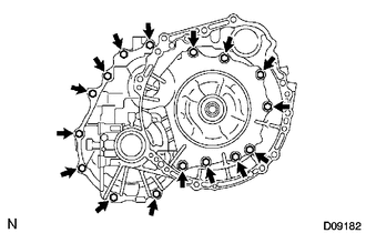
Remove the 16 bolts.
Tap on the circumference of the transaxle housing with a plastic-faced hammer to remove the transaxle housing from the transaxle.
- NOTICE:
-
Differential may be accidentally removed when the transaxle housing is removed.
34301B
31.REMOVE UNDERDRIVE CYLINDRICAL ROLLER BEARING
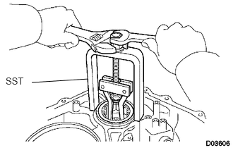
Using SST, remove the cylindrical roller bearing from the transaxle.
- SST
- 09514-35011
34346
32.REMOVE UNDERDRIVE OUTPUT SHAFT OIL SEAL RING
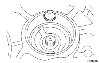
Remove the oil seal ring from the transaxle housing.
33.REMOVE OIL PUMP ASSEMBLY
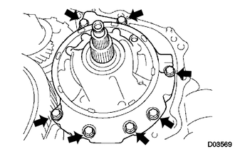
Remove the 7 bolts and oil pump assembly from the transaxle.
34736B
34.REMOVE THRUST NEEDLE ROLLER BEARING
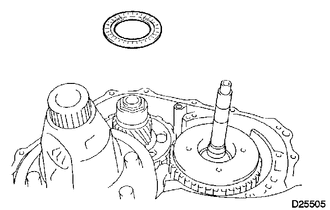
Remove thrust needle roller bearing from the underdrive planetary gear.
34736A
35.REMOVE NO. 2 THRUST BEARING UNDERDRIVE RACE
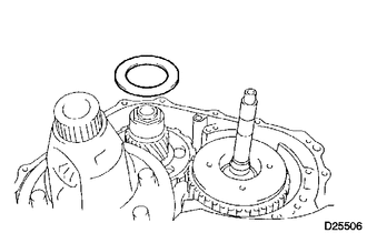
Remove the thrust bearing race from the underdrive planetary gear.
36.REMOVE FRONT DIFFERENTIAL ASSEMBLY
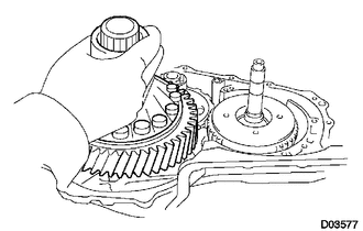
Remove the front differential from the transaxle.
35179
37.REMOVE OVERDRIVE BRAKE GASKET
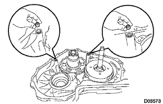
Remove the 2 overdrive brake gaskets from the transaxle.
38.REMOVE FORWARD CLUTCH ASSEMBLY
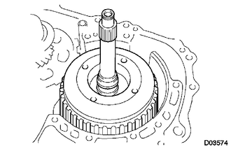
Remove the forward clutch from the transaxle.
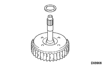
Remove the thrust bearing from the forward clutch.
35631
39.REMOVE MULTIPLE DISC CLUTCH HUB
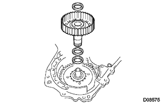
Remove the thrust bearing, multiple clutch hub, needle roller bearing and bearing race from the transaxle.
40.REMOVE UNDERDRIVE PLANETARY GEAR ASSEMBLY
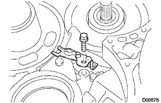
Remove the bolt and parking pawl shaft clamp.
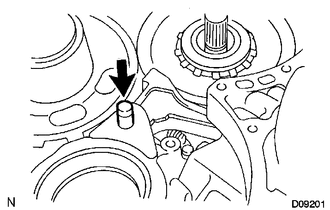
Remove the parking lock pawl shaft.
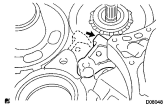
Push the parking lock pawl.
- HINT:
-
Failure to do so will cause the interference when the underdrive planetary gear is removed.
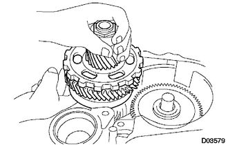
Remove the underdrive planetary gear from the transaxle.
- NOTICE:
-
Be careful so that the underdrive planetary gear assembly will not fall out.
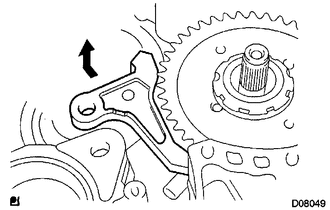
Remove the spring, pawl pin and parking lock pawl.
41.REMOVE UNDERDRIVE CLUTCH ASSEMBLY
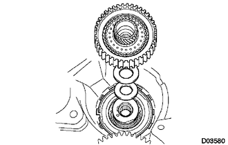
Remove the underdrive clutch assembly, needle roller bearing, thrust bearing underdrive race from the transaxle.
34360
42.REMOVE UNDERDRIVE 1-WAY CLUTCH ASSEMBLY
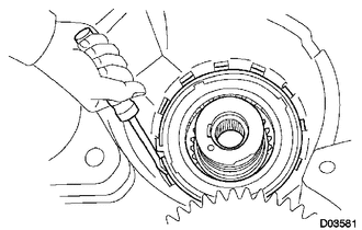
Using a screwdriver, pry out the snap ring from the transaxle.
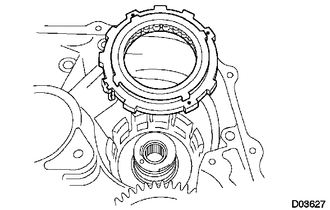
Remove the 1-way clutch from the transaxle.
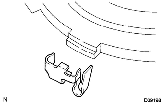
Remove the outer race retainer from the 1-way clutch.
34262
43.REMOVE NO. 2 UNDERDRIVE CLUTCH DISC
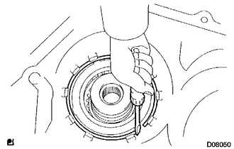
Using a screwdriver, pry out the snap ring from the transaxle.
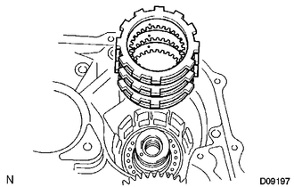
Remove the flange, 3 discs and 3 plates from the transaxle.
34262
44.INSPECT NO. 2 UNDERDRIVE CLUTCH DISC
34207
45.REMOVE UNDERDRIVE BRAKE RETURN SPRING SUB-ASSEMBLY
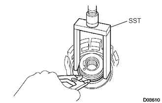
Using SST, a snap ring expander and press, remove the snap ring from the transaxle.
- SST
- 09387-00020
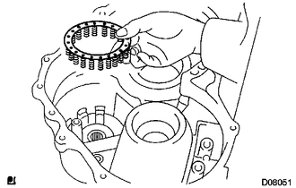
Remove the underdrive brake return spring from the underdrive brake piston.
34207
46.INSPECT UNDERDRIVE BRAKE RETURN SPRING SUB-ASSEMBLY
34244
47.REMOVE UNDERDRIVE CLUTCH DRUM OIL SEAL RING
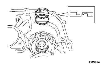
Remove the 2 oil seal rings from the transaxle.
35104Q
48.REMOVE NO. 1 TRANSAXLE CASE PLUG
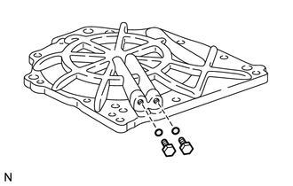
Remove the 2 plugs from the transaxle rear cover.
Remove the 2 O-rings from the 2 plugs.
35102
49.REMOVE REAR TRANSAXLE COVER SUB-ASSEMBLY
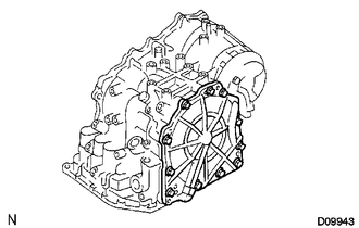
Remove the 11 bolts.
Tap the circumference of the rear cover with a plastic-faced hammer to remove the transaxle rear cover from the transaxle.
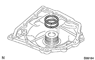
Remove the 2 outer rear clutch oil seal rings from the transaxle rear cover.
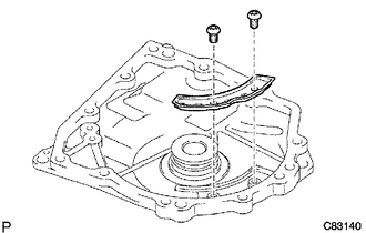
Using a T30 ''torx'' socket wrench, remove the 2 screws and transaxle rear cover plate.
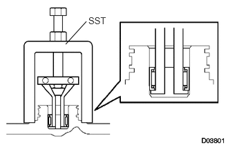
Using SST, remove the needle-roller bearing from the transaxle rear cover.
- SST
- 09387-00041 (09387-01010, 09387-01030, 09387-01040)
34253
50.REMOVE UNDERDRIVE BRAKE PISTON
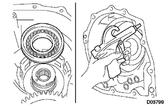
Apply compressed air (392 kPa, 4.0 kgf/cm2, 57 psi) to the transaxle case to remove the underdrive brake piston.
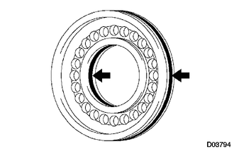
Remove the 2 O-rings from the underdrive brake piston.
35666D
51.REMOVE BRAKE APPLY TUBE
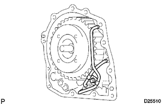
Remove the bolt, clamp and 2 brake apply tubes.
Remove the brake apply tube from the clamp.
35895
52.REMOVE FRONT CLUTCH APPLY TUBE
35148
53.REMOVE NO. 1 GOVERNOR APPLY GASKET
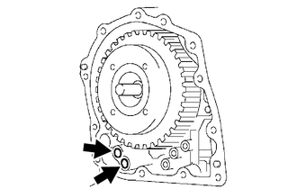
Using a screwdriver, remove the 2 governor apply gaskets.
54.REMOVE DIRECT CLUTCH ASSEMBLY
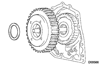
Remove the thrust bearing and direct clutch from the transaxle.
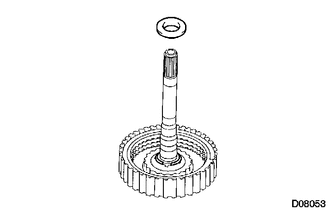
Remove the bearing race from the direct clutch.
35730
55.REMOVE REAR PLANETARY SUN GEAR ASSEMBLY
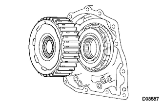
Remove the rear planetary sun gear from the transaxle.
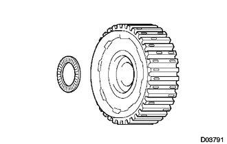
Remove the rear planetary sun gear thrust bearing from the rear planetary sun gear.
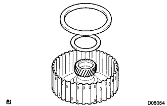
Remove the No. 1 thrust washer and 1-way clutch thrust bearing from the rear planetary sun gear.
35790
56.REMOVE 1-WAY CLUTCH ASSEMBLY
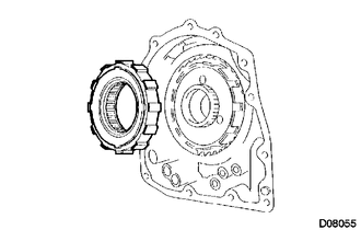
Remove the 1-way clutch from the transaxle.
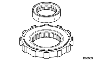
Remove the 1-way clutch inner race from the 1-way clutch.
35798A
57.REMOVE 1-WAY CLUTCH SLEEVE OUTER
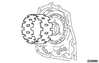
35677
58.REMOVE 2ND BRAKE CLUTCH DISC
Using a screwdriver, remove the 2nd brake hole snap ring.
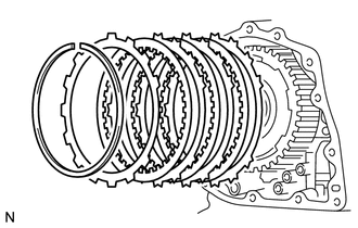
Remove the flange, 3 discs and 3 plates from the transaxle.
35677
59.INSPECT 2ND BRAKE CLUTCH DISC
60.REMOVE 2ND BRAKE PISTON ASSEMBLY
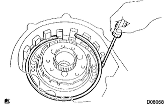
Using a screwdriver, pry out the snap ring.
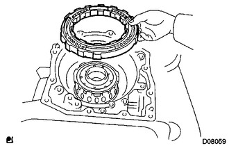
Remove the 2nd brake piston from the transaxle.
35677A
61.REMOVE 1ST AND REVERSE BRAKE CLUTCH DISC
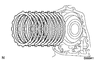
Remove the flange, 5 discs and 5 plates from the transaxle.
35677A
62.INSPECT 1ST AND REVERSE BRAKE CLUTCH DISC
35760
63.REMOVE REAR PLANETARY GEAR ASSEMBLY
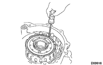
Using a screwdriver, pry out the snap ring from the brake hub.
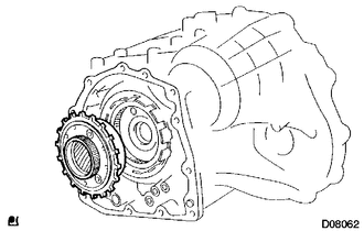
Remove the rear planetary gear from the transaxle.
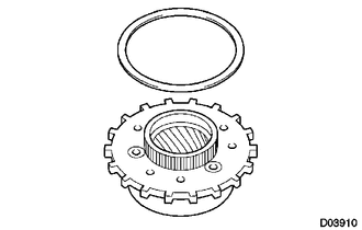
Remove the thrust washer from the rear planetary gear.
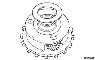
Remove the thrust bearing race from the rear planetary gear.
35714B
64.REMOVE INPUT SUN GEAR
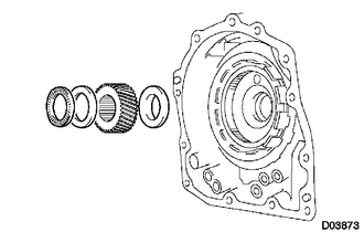
Remove the 2 thrust bearings, bearing race and input sun gear from the transaxle.
35720
65.REMOVE FRONT PLANETARY GEAR ASSEMBLY
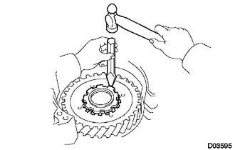
Using a chisel and hammer, unstake the lock washer.
- NOTICE:
-
Push down all claws of the washer. Otherwise SST cannot be fully pressed against the nut and cannot loosen the nut.
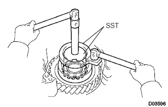
Using SST, remove the nut.
- SST
- 09387-00030
09387-00080
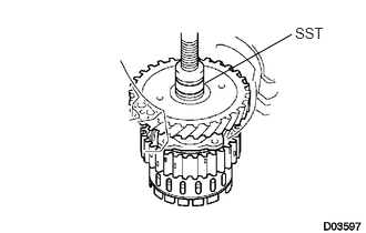
Using SST and a press, remove the front planetary gear from the counter drive gear.
- SST
- 09950-60010 (09951-00450)
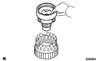
Remove the front planetary gear from the brake hub.
35743
66.REMOVE FRONT PLANETARY RING GEAR
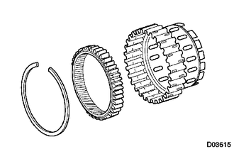
Using a screwdriver, pry out the brake hub snap ring and front planetary ring gear from the brake hub.
35623H
67.REMOVE 1ST AND REVERSE BRAKE PISTON
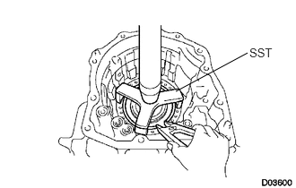
Using SST, a press and ring expander, remove the snap ring and piston return spring.
- SST
- 09387-00070
- NOTICE:
- ·
Stop the press when the spring sheet is lowered 1 to 2 mm (0.039 to 0.078 in.) from the snap ring groove, preventing the spring sheet from deforming.
·Do not expand the snap ring excessively.
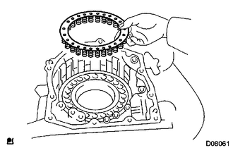
Remove the 1st and reverse brake return spring from the 1st and reverse brake piston.
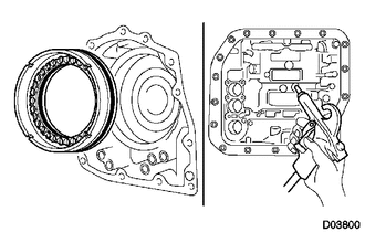
Apply compressed air (392 kPa, 4.0 kgf/cm2, 57 psi) to the transaxle to remove the 1st and reverse brake piston.
- NOTICE:
- ·
Applying compressed air may cause the piston to jump out. When removing the piston, hold it with your hand using a waste cloth.
·Make sure not to spatter ATF when applying compressed air.
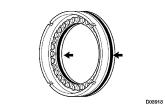
Remove the 2 O-rings from the 1st and reverse brake piston.
35068
68.INSPECT 1ST AND REVERSE BRAKE RETURN SPRING SUB-ASSEMBLY
35782C
69.REMOVE COUNTER DRIVE GEAR
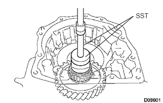
Using SST and a press, press out the counter drive gear from the transaxle.
- SST
- 09950-60010 (09951-00600)
09950-70010 (09951-07100)
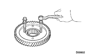
As shown in the illustration, tighten the 2 bolts evenly and make a clearance of approximately. 20.0 mm (0.797 in.) between the counter drive gear and the inner race.
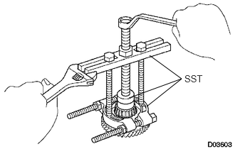
Using SST, remove the tapered roller bearing.
- SST
- 09950-60010 (09951-00600)
09950-40011 (09951-04010, 09952-04010, 09953-04020, 09954-04010, 09955-04011, 09958-04011)
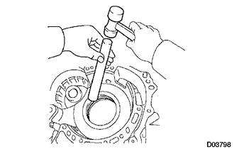
Using a brass bar and hammer, tap out the 2 counter drive gear bearing outer races from the transaxle.
35782D
70.REMOVE COUNTER DRIVE GEAR HOLE SNAP RING
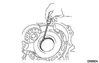
Using a screwdriver, pry out the snap ring from the transaxle.
35104C
71.REMOVE NO. 2 BREATHER PLUG
35882A
72.REMOVE DIFFERENTIAL GEAR LUBE APPLY TUBE
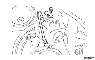
Remove the bolt, the transaxle apply tube clamp and the differential gear lube apply tube from the transaxle.