U241E AUTOMATIC TRANSMISSION / TRANSAXLE FORWARD CLUTCH REASSEMBLY
PROCEDURE

 35712A
1.INSTALL INPUT SHAFT OIL SEAL RING
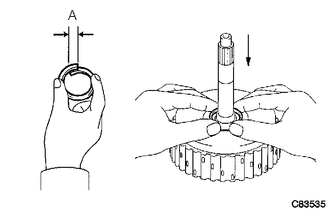
Compress the oil seal ring from both sides to reduce dimension A.
- Dimension A:
5.0 mm (0.197 in.)
Coat the oil seal ring with ATF and install it to the input shaft.
35602B
2.INSTALL FORWARD CLUTCH PISTON O-RING
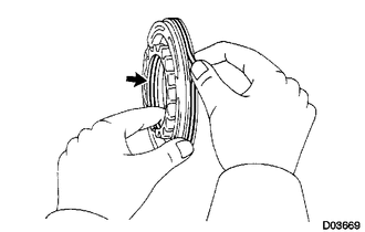
Coat 2 new O-rings with ATF, and install them to the forward clutch piston.
35602A
3.INSTALL FORWARD CLUTCH PISTON SUB-ASSEMBLY
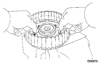
Install the forward clutch piston to the forward clutch drum.
35603A
4.INSTALL FORWARD CLUTCH RETURN SPRING SUB-ASSEMBLY
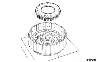
Place the forward clutch return spring onto the forward clutch piston.
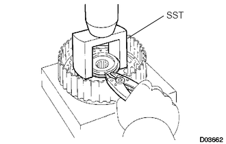
Place SST on the return spring, and compress the return spring with a press.
- SST
- 09350-32014 (09351-32070)
Install the snap ring with a snap ring expander. Be sure the end gap of the snap ring is not aligned with the spring retainer claw.
- NOTICE:
- ·
Stop the press when the spring sheet is lowered to the place 1 to 2 mm (0.039 to 0.078 in.) from the snap ring groove.
·This prevents the spring sheet from being deformed.
·Do not expand the snap ring excessively.
35675B
5.INSTALL FORWARD CLUTCH FLANGE HOLE SNAP RING
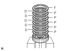
Install the 5 plates, 5 discs and flange.
- Install order:
P - D - P - D - P - D - P - D - P - D - F
- HINT:
-
P = Plate
-
D = Disc
-
F = Flange
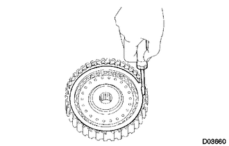
Using a screwdriver, install the snap ring.
Check that the end gap of the snap ring is not aligned with one of the cutouts.
6.INSPECT PACK CLEARANCE OF FORWARD CLUTCH
35633B
7.INSPECT FORWARD MULTIPLE DISC CLUTCH DISC
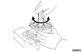
Inspect the clutch disc rotation.
After inserting the multiple disc clutch into the multiple disc clutch hub, rotate the forward clutch and check that the disc lightly rotates.
- NOTICE:
-
Do not place the forward clutch in a vise.