U241E AUTOMATIC TRANSMISSION / TRANSAXLE AUTOMATIC TRANSAXLE SYSTEM DTC CHECK / CLEAR
CHECK DTC
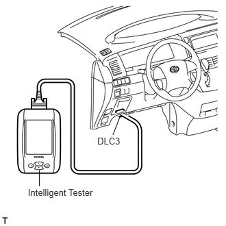
DTCs which are stored in the ECM can be displayed with the intelligent tester.
The intelligent tester can display pending DTCs and current DTCs. Some DTCs are not stored unless a malfunction is detected in consecutive driving cycles. When a malfunction is detected in only one driving cycle, it is stored as a pending DTC.
Connect the intelligent tester to the DLC3.
Turn the ignition switch on (IG) and turn the tester ON.
Enter the following menus: Powertrain / Engine and ECT / DTC / Current or Pending.
Confirm the DTCs and freeze frame data, and then write them down.
Confirm the details of the DTCs (see page Drivetrain>U241E (AUTOMATIC TRANSMISSION / TRANSAXLE)>AUTOMATIC TRANSAXLE SYSTEM>DIAGNOSTIC TROUBLE CODE CHART).
- NOTICE:
-
When simulating a symptom with the scan tool to check for DTCs, use normal mode. For codes on the DIAGNOSTIC TROUBLE CODE CHART subject to "2 trip detection logic", perform the following actions.
-
Turn the ignition switch off after the symptom is simulated once. Then repeat the simulation process. When the symptom has been simulated twice, the MIL illuminates and the DTCs are recorded in the ECM.
CLEAR DTC (Using intelligent tester)
Connect the intelligent tester to the DLC3.
Turn the ignition switch on (IG) and turn the tester ON.
Enter the following menus: Powertrain / Engine and ECT / DTC / Clear.
Press the YES button.
- HINT:
-
When operating the tester to erase the codes, the DTCs and freeze frame data will be erased.
CLEAR DTC (Without using intelligent tester)
Perform either of the following operations.
Disconnect the cable from the negative (-) battery terminal for more than 1 minute. However, if you disconnect the cable from the negative (-) battery terminal, perform the "INITIALIZATION" procedure (see page General>INTRODUCTION>REPAIR INSTRUCTION>INITIALIZATION).
Remove the EFI and ETC-S fuses from the No. 1 engine room relay block (located inside the engine compartment) for more than 1 minute.