U241E AUTOMATIC TRANSMISSION / TRANSAXLE PARK / NEUTRAL POSITION SWITCH INSTALLATION
PROCEDURE

 84540
1.INSTALL PARK/NEUTRAL POSITION SWITCH ASSEMBLY
Move the shift lever to N.
Temporarily install the park/neutral position switch assembly to the automatic transaxle assembly with the 2 bolts.
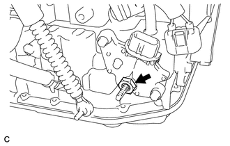
Install a new lock plate and lock nut to the park/neutral position switch assembly.
- Torque:
- 6.9 N*m (70 kgf*cm, 61 in.*lbf)
Temporarily install the control shaft lever to the manual valve lever shaft with the nut and washer.
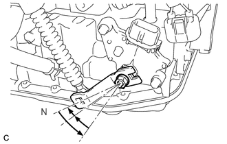
Turn the control shaft lever counterclockwise until it stops, then turn it clockwise 2 notches.
Remove the nut, washer and control shaft lever from the manual valve lever shaft.
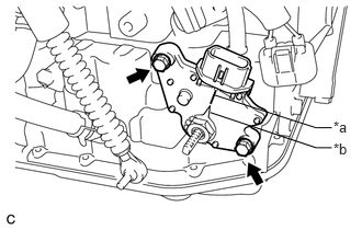
Align the indicator with the neutral basic line.
| *a | Neutral Basic Line |
| *b | Indicator |
Hold the park/neutral position switch assembly in position and tighten the 2 bolts.
- Torque:
- 5.4 N*m (55 kgf*cm, 48 in.*lbf)
Using a screwdriver, stake the lock nut with the lock plate.
Install the control shaft lever to the manual valve lever shaft with the nut and washer.
- Torque:
- 13 N*m (130 kgf*cm, 9 ft.*lbf)
Install the transmission control cable assembly to the No. 1 transmission control cable bracket with a new clip.
Connect the transmission control cable assembly to the control shaft lever with the nut.
- Torque:
- 12 N*m (122 kgf*cm, 9 ft.*lbf)
Connect the park/neutral position switch assembly connector.
2.INSTALL BATTERY
Install the battery carrier bracket with the 2 bolts.
- Torque:
- 20 N*m (204 kgf*cm, 15 ft.*lbf)
Install the battery carrier support with the 4 bolts.
- Torque:
- 20 N*m (204 kgf*cm, 15 ft.*lbf)
Install the No. 2 air cleaner inlet with the bolt.
- Torque:
- 5.0 N*m (51 kgf*cm, 44 in.*lbf)
Engage the 2 wire harness clamps.
Install the battery tray.
Install the battery.
Install the battery insulator.
Install the battery clamp sub-assembly with the bolt.
- Torque:
- 46 N*m (469 kgf*cm, 34 ft.*lbf)
Tighten the nut.
- Torque:
- 5.0 N*m (51 kgf*cm, 44 in.*lbf)
3.CONNECT CABLE TO NEGATIVE BATTERY TERMINAL
4.ADJUST SHIFT LEVER POSITION (for LHD)
Adjust the shift lever position (See page Drivetrain>U241E (AUTOMATIC TRANSMISSION / TRANSAXLE)>SHIFT LEVER(for LHD)>ADJUSTMENT).
5.ADJUST SHIFT LEVER POSITION (for RHD)
Adjust the shift lever position (See page Drivetrain>U241E (AUTOMATIC TRANSMISSION / TRANSAXLE)>SHIFT LEVER(for RHD)>ADJUSTMENT).
84540
6.INSPECT PARK/NEUTRAL POSITION SWITCH ASSEMBLY
Inspect the switch (See page Drivetrain>U241E (AUTOMATIC TRANSMISSION / TRANSAXLE)>PARK / NEUTRAL POSITION SWITCH>ON-VEHICLE INSPECTION).
7.PERFORM INITIALIZATION
Perform initialization (See page General>INTRODUCTION>REPAIR INSTRUCTION>INITIALIZATION).
- NOTICE:
-
Certain systems need to be initialized after disconnecting and reconnecting the cable from the negative (-) battery terminal.