Home › Brake › BRAKE CONTROL / DYNAMIC CONTROL SYSTEMS › VEHICLE STABILITY CONTROL SYSTEM › 2014.09–2016.05
RM24M0E _54 Brake _059583 BRAKE CONTROL / DYNAMIC CONTROL SYSTEMS _0292158 VEHICLE STABILITY CONTROL SYSTEM C

BRAKE CONTROL / DYNAMIC CONTROL SYSTEMS  VEHICLE STABILITY CONTROL SYSTEM  U0073  Control Module Communication Bus OFF  U0100  Lost Communication with ECM / PCM  U0123  Lost Communication with Yaw Rate Sensor Module  U0126  Lost Communication with Steering Angle Sensor Module  


DESCRIPTION

The skid control ECU (brake actuator assembly) receives signals from the ECM, steering angle sensor and yaw rate and acceleration sensor via CAN communication.

DTC No. Detection Item DTC Detection Condition Trouble Area
U0073 Control Module Communication Bus OFF The +BS terminal voltage is between 9.6 and a 16.5 V and a bus OFF state occurs for 0.1 seconds or more. CAN communication system
U0100 Lost Communication with ECM / PCM The +BS terminal voltage is between 9.6 and 16.5 V, the vehicle speed is 6 km/h (4 mph) or more, and signals cannot be sent to the ECM for 2 seconds or more.
·

CAN communication system

·

Skid control ECU (brake actuator assembly)

·

ECM


U0123 Lost Communication with Yaw Rate Sensor Module The +BS terminal voltage is between 9.6 and 16.5 V, the vehicle speed is 6 km/h (4 mph) or more, and signals from the yaw rate sensor cannot be received for 1 second or more.
·

CAN communication system

·

Skid control ECU (brake actuator assembly)

·

Yaw rate sensor (yaw rate and acceleration sensor)


U0126 Lost Communication with Steering Angle Sensor Module The +BS terminal voltage is between 9.6 and 16.5 V, the vehicle speed is 6 km/h (4 mph) or more, and signals from the steering angle sensor cannot be received for 1 second or more.
·

CAN communication system

·

Skid control ECU (brake actuator assembly)

·

Steering angle sensor


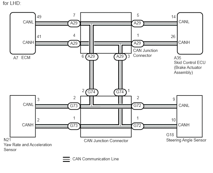
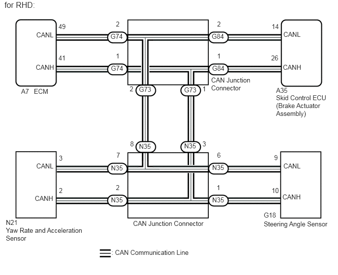
WIRING DIAGRAM

C314210E03
0.771,0.656 1.198,0.885 0.427,0.229 10 false CANL 0.771,3.438 1.198,3.667 0.427,0.229 10 false CANL 6.01,3.469 6.438,3.698 0.427,0.229 10 false CANL 6.01,0.646 6.438,0.875 0.427,0.229 10 false CANL 6,1.344 6.427,1.573 0.427,0.229 10 false CANH 5.99,4.125 6.417,4.354 0.427,0.229 10 false CANH 0.74,4.125 1.167,4.354 0.427,0.229 10 false CANH 0.76,1.344 1.188,1.573 0.427,0.229 10 false CANH 2.365,0.688 2.719,0.917 0.354,0.229 10 false A29 2.365,1.375 2.719,1.604 0.354,0.229 10 false A29 2.948,1.813 3.302,2.042 0.354,0.229 10 false A29 3.917,1.813 4.271,2.042 0.354,0.229 10 false A29 4.5,1.365 4.854,1.594 0.354,0.229 10 false A29 4.5,0.688 4.854,0.917 0.354,0.229 10 false A29 3.906,3.01 4.26,3.24 0.354,0.229 10 false G74 2.948,3.01 3.302,3.24 0.354,0.229 10 false G74 2.354,3.479 2.708,3.708 0.354,0.229 10 false G73 2.354,4.146 2.708,4.375 0.354,0.229 10 false G73 4.49,4.146 4.844,4.375 0.354,0.229 10 false G72 4.49,3.469 4.844,3.698 0.354,0.229 10 false G72 4.604,3.208 4.885,3.365 0.281,0.156 10 false 2 4.292,2.969 4.573,3.125 0.281,0.156 10 false 1 4.594,3.896 4.875,4.052 0.281,0.156 10 false 1 2.458,3.896 2.74,4.052 0.281,0.156 10 false 1 2.469,3.208 2.75,3.365 0.281,0.156 10 false 2 2.76,2.969 3.042,3.125 0.281,0.156 10 false 2 1.25,3.271 1.531,3.427 0.281,0.156 10 false 3 1.25,3.958 1.531,4.115 0.281,0.156 10 false 2 5.76,3.958 6.042,4.115 0.281,0.156 10 false 10 5.813,3.26 6.094,3.417 0.281,0.156 10 false 9 4.292,1.813 4.573,1.969 0.281,0.156 10 false 3 5.75,1.146 6.031,1.302 0.281,0.156 10 false 26 5.76,0.479 6.042,0.635 0.281,0.156 10 false 14 4.604,1.104 4.885,1.26 0.281,0.156 10 false 1 4.604,0.427 4.885,0.583 0.281,0.156 10 false 5 2.75,1.813 3.031,1.969 0.281,0.156 10 false 6 2.458,1.104 2.74,1.26 0.281,0.156 10 false 4 2.458,0.427 2.74,0.583 0.281,0.156 10 false 7 1.24,0.479 1.521,0.635 0.281,0.156 10 false 49 1.24,1.146 1.521,1.302 0.281,0.156 10 false 41 5.854,2.021 7.042,2.552 1.188,0.531 10 false Skid Control ECU (Brake Actuator Assembly) 5.854,1.865 6.135,2.021 0.281,0.156 10 false A35 0.719,1.854 1.156,2.073 0.438,0.219 10 false ECM 0.448,1.865 0.74,2.042 0.292,0.177 10 false A7 2.823,4.656 4.833,4.865 2.01,0.208 10 false CAN Junction Connector 0.125,4.792 1.854,5.167 1.729,0.375 10 false Yaw Rate and Acceleration Sensor 0.125,4.625 0.479,4.781 0.354,0.156 10 false N21 2.365,5.271 4.135,5.49 1.771,0.219 10 false : CAN Communication Line 5.594,4.635 7.052,4.906 1.458,0.271 10 false Steering Angle Sensor 5.594,4.458 5.958,4.635 0.365,0.177 10 false G18 4.479,1.615 5.375,2 0.896,0.385 10 false CAN Junction Connector 0.094,0 1.094,0.385 1,0.385 12 false for LHD:

C314210E04
0.771,0.656 1.198,0.885 0.427,0.229 10 false CANL 0.771,3.438 1.198,3.667 0.427,0.229 10 false CANL 6.01,3.438 6.438,3.667 0.427,0.229 10 false CANL 6.01,0.646 6.438,0.875 0.427,0.229 10 false CANL 6,1.344 6.427,1.573 0.427,0.229 10 false CANH 5.99,4.094 6.417,4.323 0.427,0.229 10 false CANH 0.74,4.125 1.167,4.354 0.427,0.229 10 false CANH 0.76,1.344 1.188,1.573 0.427,0.229 10 false CANH 2.344,0.688 2.698,0.917 0.354,0.229 10 false G74 2.354,1.365 2.708,1.594 0.354,0.229 10 false G74 2.948,1.813 3.302,2.042 0.354,0.229 10 false G73 3.906,1.823 4.26,2.052 0.354,0.229 10 false G73 4.5,1.365 4.854,1.594 0.354,0.229 10 false G84 4.49,0.688 4.844,0.917 0.354,0.229 10 false G84 3.906,3.01 4.26,3.24 0.354,0.229 10 false N35 2.948,3.021 3.302,3.25 0.354,0.229 10 false N35 2.354,3.479 2.708,3.708 0.354,0.229 10 false N35 2.354,4.156 2.708,4.385 0.354,0.229 10 false N35 4.5,4.156 4.854,4.385 0.354,0.229 10 false N35 4.5,3.469 4.854,3.698 0.354,0.229 10 false N35 4.604,3.208 4.885,3.365 0.281,0.156 10 false 6 4.292,2.969 4.573,3.125 0.281,0.156 10 false 3 4.594,3.896 4.875,4.052 0.281,0.156 10 false 1 2.458,3.896 2.74,4.052 0.281,0.156 10 false 2 2.469,3.208 2.75,3.365 0.281,0.156 10 false 7 2.76,2.969 3.042,3.125 0.281,0.156 10 false 8 1.25,3.271 1.531,3.427 0.281,0.156 10 false 3 1.25,3.958 1.531,4.115 0.281,0.156 10 false 2 5.76,3.958 6.042,4.115 0.281,0.156 10 false 10 5.813,3.26 6.094,3.417 0.281,0.156 10 false 9 4.292,1.802 4.573,1.958 0.281,0.156 10 false 1 5.75,1.146 6.031,1.302 0.281,0.156 10 false 26 5.76,0.479 6.042,0.635 0.281,0.156 10 false 14 4.604,1.104 4.885,1.26 0.281,0.156 10 false 1 4.604,0.427 4.885,0.583 0.281,0.156 10 false 2 2.75,1.802 3.031,1.958 0.281,0.156 10 false 2 2.458,1.104 2.74,1.26 0.281,0.156 10 false 1 2.458,0.427 2.74,0.583 0.281,0.156 10 false 2 1.24,0.479 1.521,0.635 0.281,0.156 10 false 49 1.24,1.146 1.521,1.302 0.281,0.156 10 false 41 5.854,1.99 7.042,2.521 1.188,0.531 10 false Skid Control ECU (Brake Actuator Assembly) 5.854,1.833 6.135,1.99 0.281,0.156 10 false A35 0.719,1.854 1.156,2.073 0.438,0.219 10 false ECM 0.448,1.854 0.74,2.031 0.292,0.177 10 false A7 2.823,4.656 4.833,4.865 2.01,0.208 10 false CAN Junction Connector 0.125,4.802 1.854,5.177 1.729,0.375 10 false Yaw Rate and Acceleration Sensor 0.125,4.635 0.479,4.792 0.354,0.156 10 false N21 2.365,5.271 4.135,5.49 1.771,0.219 10 false : CAN Communication Line 5.594,4.667 7.052,4.938 1.458,0.271 10 false Steering Angle Sensor 5.594,4.479 5.958,4.656 0.365,0.177 10 false G18 4.479,1.615 5.375,2 0.896,0.385 10 false CAN Junction Connector 0.094,0 1.031,0.375 0.938,0.375 12 false for RHD:

CAUTION / NOTICE / HINT

NOTICE:

When replacing the skid control ECU (brake actuator assembly), perform system variant learning and acceleration sensor zero point calibration (See page Brake>BRAKE CONTROL / DYNAMIC CONTROL SYSTEMS>VEHICLE STABILITY CONTROL SYSTEM>CALIBRATION).


PROCEDURE

1.CHECK HARNESS AND CONNECTOR (MOMENTARY INTERRUPTION)
a.

Using the GTS, check for any momentary interruption in the wire harness and connector corresponding to a DTC (See page Brake>BRAKE CONTROL / DYNAMIC CONTROL SYSTEMS>VEHICLE STABILITY CONTROL SYSTEM>CHECK FOR INTERMITTENT PROBLEMS).

ABS/VSC/TRC
Tester Display Measurement Item/Range Normal Condition Diagnostic Note
EFI Communication Open ECM communication open detection / Error or Normal Error: Momentary interruption
Normal: Normal
-
Yaw Rate Open Yaw rate sensor open detection / Error or Normal Error: Momentary interruption
Normal: Normal
-
Deceleration Open Acceleration sensor open detection / Error or Normal Error: Momentary interruption
Normal: Normal
-
Steering Open Steering angle sensor open detection / Error or Normal Error: Momentary interruption
Normal: Normal
-

Result:
Result Proceed to
There is a constant interruption. (Error is displayed without interruption.) A
There are no momentary interruptions. B
There are momentary interruptions. (Error is displayed intermittently.) C


HINT:

Perform the above inspection before disconnecting any sensors or connectors.


A

2.CHECK IF EACH CONNECTOR IS SECURELY CONNECTED (ECM, SENSOR)

B

3.RECONFIRM DTC

C

4.REPAIR OR REPLACE HARNESS OR CONNECTOR
2.CHECK IF EACH CONNECTOR IS SECURELY CONNECTED (ECM, SENSOR)
a.

Turn the engine switch off.


b.

Check if each sensor or ECM connector is securely connected.

OK:

Each connector is securely connected.


OK

3.RECONFIRM DTC

NG

CONNECT CONNECTOR TO EACH SENSOR, ECM CORRECTLY

3.RECONFIRM DTC
a.

Turn the engine switch off.


b.

Record the output DTCs (for VSC system and/or CAN communication system) (See page Brake>BRAKE CONTROL / DYNAMIC CONTROL SYSTEMS>VEHICLE STABILITY CONTROL SYSTEM>DTC CHECK / CLEAR for VSC system and/or Power Source / Network>CAN COMMUNICATION>CAN COMMUNICATION SYSTEM>DIAGNOSIS SYSTEM for CAN communication system).

HINT:

If CAN communication system DTCs and related sensor DTCs are output simultaneously, troubleshoot the DTCs (for VSC system) after the CAN communication system returns to normal.


Result:
Result Proceed to
DTCs are not output. A
DTCs are output. B
CAN communication system DTCs are output. C


A

B

C

4.REPAIR OR REPLACE HARNESS OR CONNECTOR
a.

Turn the engine switch off.


b.

Repair or replace the harness or connector.


c.

Check for any momentary interruptions between the skid control ECU (brake actuator assembly) and each sensor or ECM (See page Brake>BRAKE CONTROL / DYNAMIC CONTROL SYSTEMS>VEHICLE STABILITY CONTROL SYSTEM>CHECK FOR INTERMITTENT PROBLEMS).


NEXT

5.RECONFIRM DTC
5.RECONFIRM DTC
a.

Turn the engine switch off.


c.

Turn the engine switch off.


d.

Start the engine.


e.

Drive the vehicle at a speed of 15 km/h (9 mph) or more and turn the steering wheel to the right and left.


f.

Check that no CAN communication system DTCs are output (See page Power Source / Network>CAN COMMUNICATION>CAN COMMUNICATION SYSTEM>DIAGNOSIS SYSTEM).


g.

If VSC system DTCs are output, record them (See page Brake>BRAKE CONTROL / DYNAMIC CONTROL SYSTEMS>VEHICLE STABILITY CONTROL SYSTEM>DTC CHECK / CLEAR).

Result:
Result Proceed to
DTCs are not output. A
DTCs are output. B
CAN communication system DTCs are output. C


A

END

B

C