THEFT DETERRENT THEFT DETERRENT SYSTEM IG Power Source Circuit
DESCRIPTION
When the ignition switch is turned on (IG), positive (+) battery voltage is applied to the certification ECU.
WIRING DIAGRAM
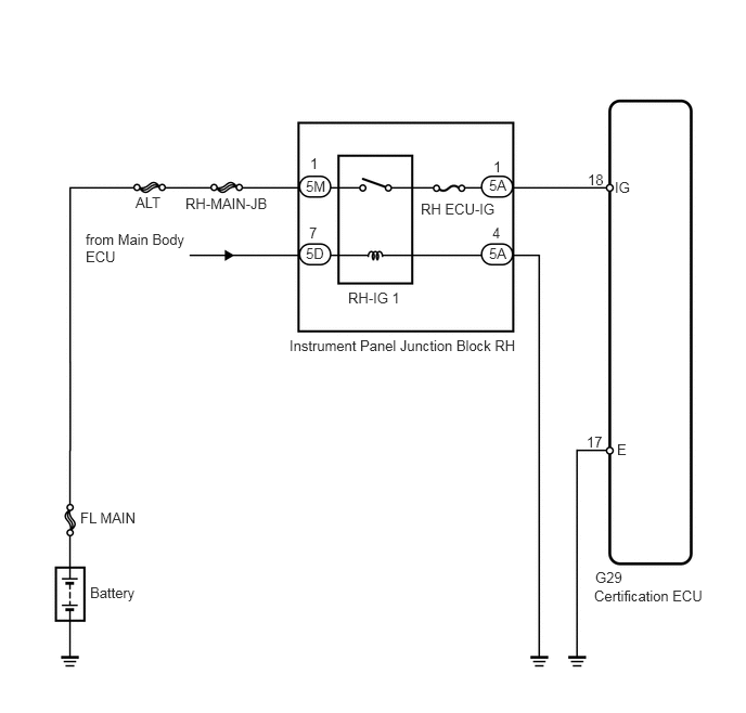
PROCEDURE
Check the basic function of the push-button start function.
- OK:
Basic function operates normally.
Proceed to the next step based on the inspection result.
- Result:
Result Proceed to OK A NG (for 2AZ-FE) B NG (for 2GR-FE) C
A
B
(See pageEngine / Hybrid System>2AZ-FE STARTING>SMART ENTRY AND START SYSTEM>PROBLEM SYMPTOMS TABLE)
C
(See pageEngine / Hybrid System>2GR-FE STARTING>SMART ENTRY AND START SYSTEM>PROBLEM SYMPTOMS TABLE)
Remove the RH ECU-IG fuse from the instrument panel junction block RH.
Measure the resistance of the fuses.
- Standard resistance:
Below 1 Ω
OK
NG
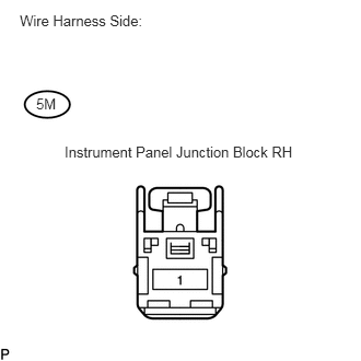
Disconnect the 5M junction block connector.
Measure the voltage of the wire harness side connector.
- Standard voltage:
Tester Connection Specified Condition 5M-1 - Body ground 10 to 14 V
OK
NG
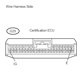
Disconnect the G29 ECU connector.
Measure the resistance of the wire harness side connector.
- Standard resistance:
Tester Connection Specified Condition G29-17 (E) - Body ground Below 1 Ω
Measure the voltage of the wire harness side connector.
- Standard voltage:
Tester Connection Condition Specified Condition G29-18 (IG) - Body ground Ignition switch off Below 1 V Ignition switch on (IG) 10 to 14 V
OK
NG