RM24M0E
_58
Vehicle Interior
_059587
METER / GAUGE / DISPLAY
_0292197
METER / GAUGE SYSTEM
J
METER / GAUGE / DISPLAY METER / GAUGE SYSTEM Clock Display Circuit
DESCRIPTION
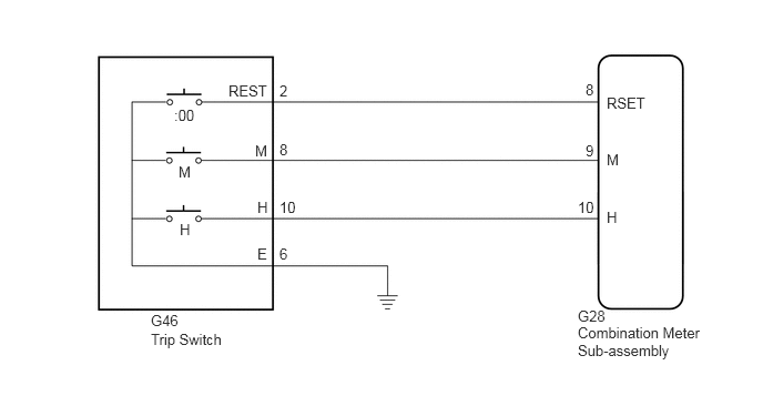
The clock display (combination meter sub-assembly) can be adjusted by pressing the clock switch on the trip switch.
WIRING DIAGRAM
1.635,1 1.854,1.156
0.219,0.156
10
false
:00
2.146,0.771 2.635,0.927
0.49,0.156
10
false
REST
2.625,0.771 2.729,0.927
0.104,0.156
10
false
2
2.417,2.302 2.531,2.458
0.115,0.156
10
false
E
2.625,2.302 2.802,2.458
0.177,0.156
10
false
6
5.5,0.76 5.594,0.917
0.094,0.156
10
false
8
5.698,0.885 6.198,1.042
0.5,0.156
10
false
RSET
1.677,1.531 1.823,1.688
0.146,0.156
10
false
M
2.396,1.333 2.531,1.49
0.135,0.156
10
false
M
2.625,1.323 2.729,1.479
0.104,0.156
10
false
8
5.5,1.333 5.594,1.49
0.094,0.156
10
false
9
5.698,1.417 5.833,1.573
0.135,0.156
10
false
M
1.688,2.073 1.813,2.229
0.125,0.156
10
false
H
2.417,1.865 2.542,2.021
0.125,0.156
10
false
H
2.625,1.865 2.844,2.021
0.219,0.156
10
false
10
5.427,1.865 5.604,2.021
0.177,0.156
10
false
10
5.698,1.958 5.833,2.115
0.135,0.156
10
false
H
5.427,2.885 5.719,3.042
0.292,0.156
10
false
G28
5.427,3.042 6.667,3.552
1.24,0.51
10
false
Combination Meter Sub-assembly
1.417,2.927 1.708,3.083
0.292,0.156
10
false
G46
1.417,3.104 2.125,3.26
0.708,0.156
10
false
Trip Switch
PROCEDURE
1.READ VALUE USING GTS (TIMER SWITCH M, H, 00 ON COMBINATION METER)
a.
Connect the GTS to the DLC3.
b.
Turn the engine switch on (IG).
c.
Turn the GTS on.
d.
Enter the following menus: Body Electrical / Combination Meter / Data List.
e.
Read the Data List according to the display on the GTS.
| Tester Display | Measurement Item/Range | Normal Condition | Diagnostic Note |
|---|---|---|---|
| Timer Switch M on Combination Meter | Clock switch "M" / ON or OFF | ON: Switch pushed
OFF: Switch released |
- |
| Timer Switch H on Combination Meter | Clock switch "H" / ON or OFF | ON: Switch pushed
OFF: Switch released |
- |
| Timer Switch 00 on Combination Meter | Clock switch "00" / ON or OFF | ON: Switch pushed
OFF: Switch released |
- |
- OK:
Clock switch condition displayed on the GTS changes with the actual switch operation.
OK
REPLACE COMBINATION METER SUB-ASSEMBLY
NG
2.INSPECT TRIP SWITCH
2.INSPECT TRIP SWITCH
a.
2.063,1.552 2.604,1.552
false
0.813,1.573 1.354,1.573
false
1.719,1.927 1.719,1.583
false
1.896,1.25 1.896,0.594
false
2.667,1.479 3.063,1.635
0.396,0.156
10
false
E
0.646,1.5 0.813,1.656
0.167,0.156
10
false
H
1.677,1.938 1.813,2.094
0.135,0.156
10
false
M
1.75,0.417 2.219,0.573
0.469,0.156
10
false
REST
0.073,0.073 0.24,0.229
0.167,0.156
10
false
*a
Remove the trip switch (see page Vehicle Interior>LIGHTING>HAZARD WARNING SWITCH>REMOVAL).
b.
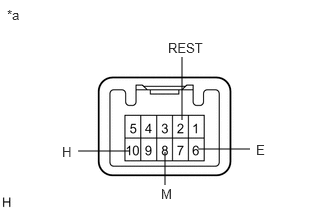
Measure the resistance according to the value(s) in the table below.
- Standard Resistance:
Tester Connection Condition Specified Condition 10 (H) - 6 (E) Clock switch "H" pressed Below 1 Ω Clock switch "H" not pressed 10 kΩ or higher 8 (M) - 6 (E) Clock switch "M" pressed Below 1 Ω Clock switch "M" not pressed 10 kΩ or higher 2 (REST) - 6 (E) Clock switch "00" pressed Below 1 Ω Clock switch "00" not pressed 10 kΩ or higher
| *a | Component without harness connected
(Trip Switch) |
OK
3.CHECK WIRE HARNESS AND CONNECTOR (COMBINATION METER SUB-ASSEMBLY - TRIP SWITCH)
NG
3.CHECK WIRE HARNESS AND CONNECTOR (COMBINATION METER SUB-ASSEMBLY - TRIP SWITCH)
a.
Disconnect the G28 combination meter sub-assembly connector.
b.
Measure the resistance according to the value(s) in the table below.
- Standard Resistance:
Tester Connection Condition Specified Condition G28-10 (H) - G46-10 (H) Always Below 1 Ω G28-10 (H) or G46-10 (H) - Body ground Always 10 kΩ or higher G28-9 (M) - G46-8 (M) Always Below 1 Ω G28-9 (M) or G46-8 (M) - Body ground Always 10 kΩ or higher G28-8 (RSET) - G46-2 (REST) Always Below 1 Ω G28-8 (RSET) or G46-2 (REST) - Body ground Always 10 kΩ or higher G46-6 (E) - Body ground Always Below 1 Ω
OK
REPLACE COMBINATION METER SUB-ASSEMBLY
NG
REPAIR OR REPLACE HARNESS OR CONNECTOR