Home › Vehicle Interior › METER / GAUGE / DISPLAY › METER / GAUGE SYSTEM › from 2016.05
RM24M0E _58 Vehicle Interior _059587 METER / GAUGE / DISPLAY _0292197 METER / GAUGE SYSTEM C

METER / GAUGE / DISPLAY  METER / GAUGE SYSTEM  B1508  Short in Turn Signal / Hazard Flasher Circuit  


DESCRIPTION

This DTC is stored when the combination meter sub-assembly detects an short in a turn signal light circuit.

HINT:

If there is a short in a turn signal light circuit, all of the turn signal lights on the side with the short circuit will not blink.


DTC No. DTC Detection Condition Trouble Area Note
B1508 When IG voltage is 7 V or more and the following condition is detected:
·

Short in turn signal light circuit


·

Bulb

·

LED

·

Harness or connector

·

Instrument panel junction block LH

·

Instrument panel junction block RH

·

Combination meter sub-assembly


w/ Multi-information Display

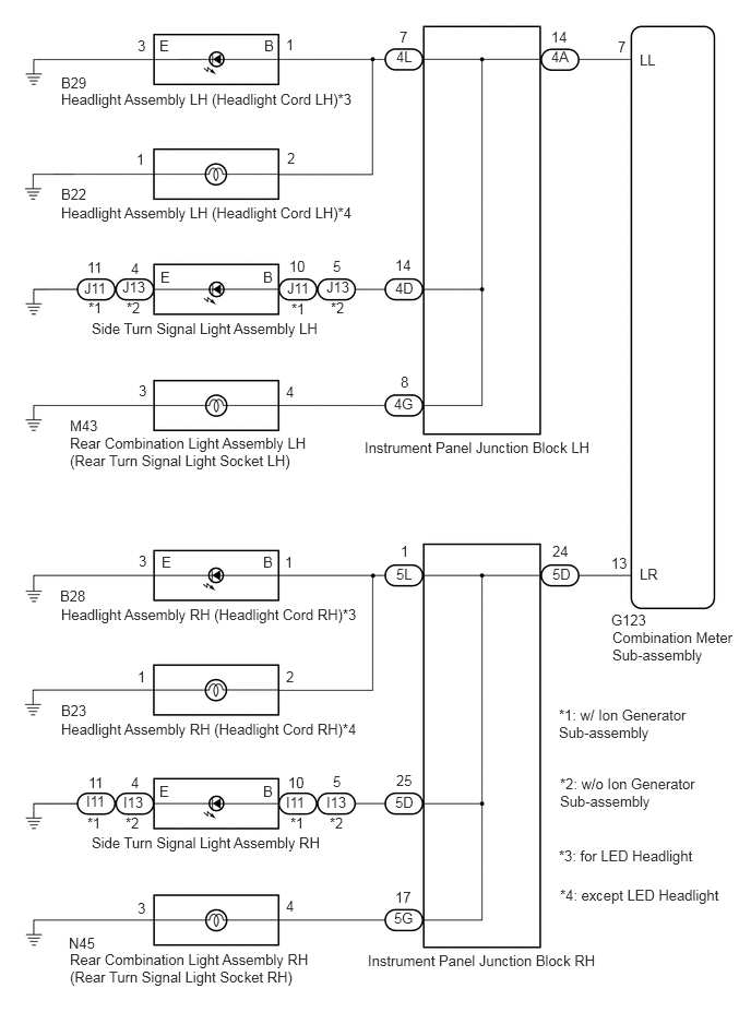
WIRING DIAGRAM

E349769E05
5.844,6 7.021,6.573 1.177,0.573 10 false Combination Meter Sub-assembly 5.833,5.833 6.229,6.146 0.396,0.313 10 false G123 6.104,0.49 6.719,0.854 0.615,0.365 10 false LL 6.104,5.396 6.656,5.698 0.552,0.302 10 false LR 3.781,0.458 4.396,0.823 0.615,0.365 10 false 4L 5.26,0.458 5.875,0.823 0.615,0.365 10 false 4A 3.76,3.771 4.375,4.135 0.615,0.365 10 false 4G 3.771,2.667 4.385,3.031 0.615,0.365 10 false 4D 5.271,5.396 5.885,5.76 0.615,0.365 10 false 5D 3.771,7.573 4.385,7.938 0.615,0.365 10 false 5D 3.781,5.396 4.396,5.76 0.615,0.365 10 false 5L 3.76,8.677 4.375,9.042 0.615,0.365 10 false 5G 3.813,0.271 4.125,0.521 0.313,0.25 10 false 7 5.896,0.365 6.208,0.615 0.313,0.25 10 false 7 5.26,0.271 5.573,0.521 0.313,0.25 10 false 14 3.771,2.448 4.083,2.698 0.313,0.25 10 false 14 3.823,3.563 4.135,3.813 0.313,0.25 10 false 8 5.271,5.177 5.583,5.427 0.313,0.25 10 false 24 3.781,7.365 4.094,7.615 0.313,0.25 10 false 25 3.823,5.177 4.135,5.427 0.313,0.25 10 false 1 3.771,8.479 4.083,8.729 0.313,0.25 10 false 17 2.521,0.354 2.75,0.604 0.229,0.25 10 false B 1.521,0.354 1.75,0.604 0.229,0.25 10 false E 2.729,0.344 2.958,0.594 0.229,0.25 10 false 1 1.313,0.354 1.542,0.604 0.229,0.25 10 false 3 1.302,1.438 1.531,1.688 0.229,0.25 10 false 1 2.74,1.427 2.969,1.677 0.229,0.25 10 false 2 2.51,2.563 2.74,2.813 0.229,0.25 10 false B 1.531,2.563 1.76,2.813 0.229,0.25 10 false E 1.542,5.281 1.771,5.531 0.229,0.25 10 false E 2.51,5.281 2.74,5.531 0.229,0.25 10 false B 3.177,2.458 3.365,2.708 0.188,0.25 10 false 5 2.76,2.458 3.052,2.708 0.292,0.25 10 false 10 0.833,2.469 1.021,2.719 0.188,0.25 10 false 11 1.25,2.479 1.438,2.729 0.188,0.25 10 false 4 2.729,3.656 2.958,3.906 0.229,0.25 10 false 4 1.323,3.646 1.552,3.896 0.229,0.25 10 false 3 2.719,5.281 2.948,5.531 0.229,0.25 10 false 1 1.323,5.271 1.552,5.521 0.229,0.25 10 false 3 2.729,6.375 2.958,6.625 0.229,0.25 10 false 2 1.313,6.375 1.542,6.625 0.229,0.25 10 false 1 2.729,8.563 2.958,8.813 0.229,0.25 10 false 4 1.313,8.583 1.542,8.833 0.229,0.25 10 false 3 0.583,0.865 3.5,1.25 2.917,0.385 10 false Headlight Assembly LH (Headlight Cord LH)*3 0.583,0.708 1.021,0.958 0.438,0.25 10 false B29 0.583,1.948 3.5,2.333 2.917,0.385 10 false Headlight Assembly LH (Headlight Cord LH)*4 0.583,1.771 1.021,2.021 0.438,0.25 10 false B22 0.875,3.052 3.229,3.438 2.354,0.385 10 false Side Turn Signal Light Assembly LH 0.667,4.146 3.094,4.531 2.427,0.385 10 false Rear Combination Light Assembly LH (Rear Turn Signal Light Socket LH) 0.667,3.979 1.104,4.229 0.438,0.25 10 false M43 0.583,5.781 3.5,6.167 2.917,0.385 10 false Headlight Assembly RH (Headlight Cord RH)*3 0.573,5.604 1.01,5.854 0.438,0.25 10 false B28 0.583,6.875 3.5,7.26 2.917,0.385 10 false Headlight Assembly RH (Headlight Cord RH)*4 0.583,6.698 1.021,6.948 0.438,0.25 10 false B23 0.667,9.073 3.052,9.458 2.385,0.385 10 false Rear Combination Light Assembly RH (Rear Turn Signal Light Socket RH) 0.656,8.917 1.094,9.167 0.438,0.25 10 false N45 5.333,6.74 6.656,7.406 1.323,0.667 10 false *1: w/ Ion Generator Sub-assembly 5.344,7.396 6.813,8.094 1.469,0.698 10 false *2: w/o Ion Generator Sub-assembly 5.333,8.083 6.781,8.469 1.448,0.385 10 false *3: for LED Headlight 5.344,8.458 7.146,8.844 1.802,0.385 10 false *4: except LED Headlight 3.479,4.188 5.802,4.573 2.323,0.385 10 false Instrument Panel Junction Block LH 3.51,9.083 5.833,9.469 2.323,0.385 10 false Instrument Panel Junction Block RH 2.781,2.865 2.969,3.063 0.188,0.198 10 false *1 0.844,2.854 1.031,3.052 0.188,0.198 10 false *1 3.156,2.854 3.333,3.052 0.177,0.198 10 false *2 1.208,2.854 1.385,3.052 0.177,0.198 10 false *2 2.74,2.667 3.063,2.917 0.323,0.25 10 false J11 0.802,2.667 1.125,2.917 0.323,0.25 10 false J11 3.115,2.656 3.438,2.906 0.323,0.25 10 false J13 1.167,2.656 1.49,2.906 0.323,0.25 10 false J13 2.51,7.469 2.74,7.719 0.229,0.25 10 false B 1.521,7.469 1.75,7.719 0.229,0.25 10 false E 3.177,7.375 3.365,7.625 0.188,0.25 10 false 5 2.75,7.385 3.042,7.635 0.292,0.25 10 false 10 0.844,7.385 1.031,7.635 0.188,0.25 10 false 11 1.25,7.385 1.438,7.635 0.188,0.25 10 false 4 0.875,7.958 3.24,8.344 2.365,0.385 10 false Side Turn Signal Light Assembly RH 2.771,7.771 2.958,7.969 0.188,0.198 10 false *1 0.833,7.771 1.021,7.969 0.188,0.198 10 false *1 3.146,7.771 3.323,7.969 0.177,0.198 10 false *2 1.198,7.771 1.375,7.969 0.177,0.198 10 false *2 2.729,7.573 3.052,7.823 0.323,0.25 10 false I11 0.823,7.563 1.146,7.813 0.323,0.25 10 false I11 3.115,7.573 3.438,7.823 0.323,0.25 10 false I13 1.177,7.573 1.5,7.823 0.323,0.25 10 false I13 5.833,5.292 6.146,5.542 0.313,0.25 10 false 13

CAUTION / NOTICE / HINT

Inspect the LEDs and bulbs for this system before performing the following procedure.

Side turn signal light assembly: See page Vehicle Interior>LIGHTING>SIDE TURN SIGNAL LIGHT ASSEMBLY>INSPECTION

PROCEDURE

1.INSPECT LIGHTS
a.

Inspect the illumination of each turn signal light.

Result:
Result Proceed to
All LH turn signal lights do not blink A
All RH turn signal lights do not blink B


A

2.CHECK HARNESS AND CONNECTOR (COMBINATION METER SUB-ASSEMBLY - INSTRUMENT PANEL JUNCTION BLOCK LH)

B

7.CHECK HARNESS AND CONNECTOR (COMBINATION METER SUB-ASSEMBLY - INSTRUMENT PANEL JUNCTION BLOCK RH)
2.CHECK HARNESS AND CONNECTOR (COMBINATION METER SUB-ASSEMBLY - INSTRUMENT PANEL JUNCTION BLOCK LH)
a.

Disconnect the G123 combination meter sub-assembly connector.


b.

Disconnect the 4A instrument panel junction block LH connector.


c.

Measure the resistance according to the value(s) in the table below.

Standard Resistance:
Tester Connection Condition Specified Condition
G123-7 (LL) - 4A-14 Always 10 kΩ or higher


OK

3.CHECK HARNESS AND CONNECTOR (HEADLIGHT ASSEMBLY LH - INSTRUMENT PANEL JUNCTIONBLOCK LH)

NG

REPAIR OR REPLACE HARNESS AND CONNECTOR

3.CHECK HARNESS AND CONNECTOR (HEADLIGHT ASSEMBLY LH - INSTRUMENT PANEL JUNCTIONBLOCK LH)
a.

Disconnect the B29*1 or B22*2 headlight assembly LH (headlight cord LH) connector.


b.

Disconnect the 4L instrument panel junction block LH connector.


c.

Measure the resistance according to the value(s) in the table below.

Standard Resistance:
Tester Connection Condition Specified Condition
B29-1 (B) or 4L-7 - Body ground*1 Always 10 kΩ or higher
B22-2 or 4L-7 - Body ground*2 Always 10 kΩ or higher


HINT:

*1: for LED Headlight

*1: except LED Headlight


OK

4.CHECK HARNESS AND CONNECTOR (SIDE TURN SIGNAL LIGHT ASSEMBLY LH - INSTRUMENT PANEL JUNCTION BLOCK LH)

NG

REPAIR OR REPLACE HARNESS AND CONNECTOR

4.CHECK HARNESS AND CONNECTOR (SIDE TURN SIGNAL LIGHT ASSEMBLY LH - INSTRUMENT PANEL JUNCTION BLOCK LH)
a.

Disconnect the J11*1 or J13*2 side turn signal light assembly LH connector.


b.

Disconnect the 4D instrument panel junction block LH connector.


c.

Measure the resistance according to the value(s) in the table below.

Standard Resistance:
Tester Connection Condition Specified Condition
J11-10 (B) or 4D-14 - Body ground*1 Always 10 kΩ or higher
J13-5 (B) or 4D-14 - Body ground*2 Always 10 kΩ or higher


HINT:

*1: w/ Ion Generator Sub-assembly

*2: w/o Ion Generator Sub-assembly


OK

5.CHECK HARNESS AND CONNECTOR (REAR COMBINATION LIGHT ASSEMBLY LH - INSTRUMENT PANEL JUNCTION BLOCK LH)

NG

REPAIR OR REPLACE HARNESS AND CONNECTOR

5.CHECK HARNESS AND CONNECTOR (REAR COMBINATION LIGHT ASSEMBLY LH - INSTRUMENT PANEL JUNCTION BLOCK LH)
a.

Disconnect the M43 rear combination light assembly LH (rear turn signal light socket LH) connector.


b.

Disconnect the 4G instrument panel junction block LH connector.


c.

Measure the resistance according to the value(s) in the table below.

Standard Resistance:
Tester Connection Condition Specified Condition
M43-4 or 4G-8 - Body ground Always 10 kΩ or higher


OK

6.INSPECT INSTRUMENT PANEL JUNCTION BLOCK LH

NG

REPAIR OR REPLACE HARNESS AND CONNECTOR

6.INSPECT INSTRUMENT PANEL JUNCTION BLOCK LH
NOTICE:

Make sure to perform this step with the instrument panel junction block LH installed to the vehicle.
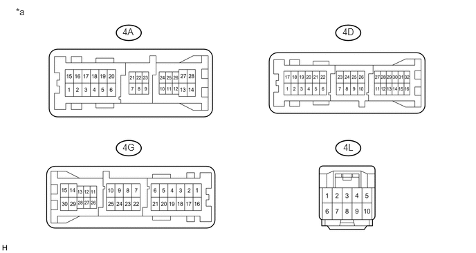

U189990E02
1.844,0.396 2.177,0.563 0.333,0.167 10 false 4A 5.156,0.396 5.49,0.563 0.333,0.167 10 false 4D 1.844,2.135 2.177,2.302 0.333,0.167 10 false 4G 5.167,2.135 5.5,2.302 0.333,0.167 10 false 4L 0.24,0.094 0.573,0.26 0.333,0.167 10 false *a

a.

Measure the resistance according to the value(s) in the table below.

Standard Resistance:
Tester Connection Condition Specified Condition
4A-14, 4L-7, 4D-14 or 4G-8 - Body ground Always 10 kΩ or higher


Text in Illustration
*a Component without harness connected
(Instrument Panel Junction Block LH)
- -


OK

REPLACE COMBINATION METER SUB-ASSEMBLY

NG

REPLACE INSTRUMENT PANEL JUNCTION BLOCK LH

7.CHECK HARNESS AND CONNECTOR (COMBINATION METER SUB-ASSEMBLY - INSTRUMENT PANEL JUNCTION BLOCK RH)
a.

Disconnect the G123 combination meter sub-assembly connector.


b.

Disconnect the 5D instrument panel junction block RH connector.


c.

Measure the resistance according to the value(s) in the table below.

Standard Resistance:
Tester Connection Condition Specified Condition
G123-13 (LR) - 5D-24 Always 10 kΩ or higher


OK

8.CHECK HARNESS AND CONNECTOR (HEADLIGHT ASSEMBLY RH - INSTRUMENT PANEL JUNCTION BLOCK RH)

NG

REPAIR OR REPLACE HARNESS AND CONNECTOR

8.CHECK HARNESS AND CONNECTOR (HEADLIGHT ASSEMBLY RH - INSTRUMENT PANEL JUNCTION BLOCK RH)
a.

Disconnect the B28*1 or B23*2 headlight assembly RH (headlight cord RH) connector.


b.

Disconnect the 5L instrument panel junction block RH connector.


c.

Measure the resistance according to the value(s) in the table below.

Standard Resistance:
Tester Connection Condition Specified Condition
B28-1 (B) or 5L-1 - Body ground*1 Always 10 kΩ or higher
B23-2 or 5L-1 - Body ground*2 Always 10 kΩ or higher


HINT:

*1: for LED Headlight

*2: except LED Headlight


OK

9.CHECK HARNESS AND CONNECTOR (SIDE TURN SIGNAL LIGHT ASSEMBLY RH - INSTRUMENT PANEL JUNCTION BLOCK RH)

NG

REPAIR OR REPLACE HARNESS AND CONNECTOR

9.CHECK HARNESS AND CONNECTOR (SIDE TURN SIGNAL LIGHT ASSEMBLY RH - INSTRUMENT PANEL JUNCTION BLOCK RH)
a.

Disconnect the I11*1 or I13*2 side turn signal light assembly RH connector.


b.

Disconnect the 5L instrument panel junction block RH connector.


c.

Measure the resistance according to the value(s) in the table below.

Standard Resistance:
Tester Connection Condition Specified Condition
I11-10 (B) or 5L-1 - Body ground*1 Always 10 kΩ or higher
I13-5 (B) or 5L-1 - Body ground*2 Always 10 kΩ or higher


HINT:

*1: w/ Ion Generator Sub-assembly

*2: w/o Ion Generator Sub-assembly


OK

10.CHECK HARNESS AND CONNECTOR (REAR COMBINATION LIGHT ASSEMBLY RH - INSTRUMENT PANEL JUNCTION BLOCK RH)

NG

REPAIR OR REPLACE HARNESS AND CONNECTOR

10.CHECK HARNESS AND CONNECTOR (REAR COMBINATION LIGHT ASSEMBLY RH - INSTRUMENT PANEL JUNCTION BLOCK RH)
a.

Disconnect the N45 rear combination light assembly RH (rear turn signal light socket RH) connector.


b.

Disconnect the 5G instrument panel junction block RH connector.


c.

Measure the resistance according to the value(s) in the table below.

Standard Resistance:
Tester Connection Condition Specified Condition
N45-4 or 5G-17 - Body ground Always 10 kΩ or higher


OK

11.INSPECT INSTRUMENT PANEL JUNCTION BLOCK RH

NG

REPAIR OR REPLACE HARNESS AND CONNECTOR

11.INSPECT INSTRUMENT PANEL JUNCTION BLOCK RH
NOTICE:

Make sure to perform this step with the instrument panel junction block RH installed to the vehicle.
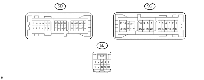

U189991E02
2.031,0.125 2.365,0.292 0.333,0.167 10 false 5D 5.167,0.125 5.5,0.292 0.333,0.167 10 false 5G 3.51,1.5 3.844,1.667 0.333,0.167 10 false 5L

a.

Measure the resistance according to the value(s) in the table below.

Standard Resistance:
Tester Connection Condition Specified Condition
5D-24, 5L-1, 5D-25 or 5G-17 - Body ground Always 10 kΩ or higher


Text in Illustration
*a Component without harness connected
(Instrument Panel Junction Block RH)
- -


OK

REPLACE COMBINATION METER SUB-ASSEMBLY

NG

REPLACE INSTRUMENT PANEL JUNCTION BLOCK RH