Home › Audio / Visual / Telematics › NAVIGATION / MULTI INFO DISPLAY › NAVIGATION SYSTEM
RM24M0E _56 Audio / Visual / Telematics _059588 NAVIGATION / MULTI INFO DISPLAY _0292199 NAVIGATION SYSTEM J

NAVIGATION / MULTI INFO DISPLAY  NAVIGATION SYSTEM  Speaker Circuit  


DESCRIPTION

If there is a short in a speaker circuit, the navigation receiver assembly detects it and stops output to the speakers.

Thus sound cannot be heard from the speakers even if there is no malfunction in the navigation receiver assembly or speakers.


WIRING DIAGRAM
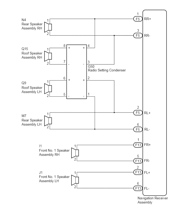
E251385E02
5.479,0.469 5.646,0.625 0.167,0.156 10 false 1 5.771,0.667 6.177,0.823 0.406,0.156 10 false RR+ 5.771,1.333 6.146,1.49 0.375,0.156 10 false RR- 5.438,0.677 5.708,0.833 0.271,0.156 10 false F5 5.438,1.333 5.667,1.49 0.229,0.156 10 false F5 5.49,1.135 5.667,1.292 0.177,0.156 10 false 3 5.49,4.208 5.656,4.365 0.167,0.156 10 false 2 5.771,4.427 6.177,4.583 0.406,0.156 10 false RL+ 5.781,5.083 6.156,5.24 0.375,0.156 10 false RL- 5.438,4.417 5.656,4.573 0.219,0.156 10 false F5 5.438,5.094 5.656,5.25 0.219,0.156 10 false F5 5.49,4.896 5.667,5.052 0.177,0.156 10 false 6 5.51,7.833 6.813,8.24 1.302,0.406 10 false Navigation Receiver Assembly 1.875,0.729 1.979,0.885 0.104,0.156 10 false 1 1.875,1.26 1.979,1.417 0.104,0.156 10 false 2 2.969,5.75 3.073,5.906 0.104,0.156 10 false 1 2.969,6.281 3.073,6.438 0.104,0.156 10 false 2 2.969,6.823 3.073,6.979 0.104,0.156 10 false 1 2.969,7.385 3.073,7.542 0.104,0.156 10 false 2 0.865,0.875 1.781,1.25 0.917,0.375 10 false Rear Speaker Assembly RH 0.865,0.708 1.125,0.865 0.26,0.156 10 false N4 1.875,1.885 1.979,2.042 0.104,0.156 10 false 1 1.875,2.448 1.979,2.604 0.104,0.156 10 false 2 3.51,1.74 3.615,1.896 0.104,0.156 10 false 4 3.51,2.396 3.615,2.552 0.104,0.156 10 false 3 2.542,1.74 2.646,1.896 0.104,0.156 10 false 8 2.542,2.375 2.646,2.531 0.104,0.156 10 false 7 2.542,3.042 2.646,3.198 0.104,0.156 10 false 6 2.542,3.688 2.646,3.844 0.104,0.156 10 false 5 3.51,3.031 3.615,3.188 0.104,0.156 10 false 2 3.51,3.677 3.615,3.833 0.104,0.156 10 false 1 0.865,2.042 1.781,2.417 0.917,0.375 10 false Roof Speaker Assembly RH 0.865,1.865 1.208,2.021 0.344,0.156 10 false Q15 1.875,3.177 1.979,3.333 0.104,0.156 10 false 1 1.875,3.74 1.979,3.896 0.104,0.156 10 false 2 0.865,3.417 1.781,3.792 0.917,0.375 10 false Roof Speaker Assembly LH 0.865,3.229 1.208,3.385 0.344,0.156 10 false Q9 1.875,4.469 1.979,4.625 0.104,0.156 10 false 1 1.875,4.99 1.979,5.146 0.104,0.156 10 false 2 0.865,4.719 1.781,5.094 0.917,0.375 10 false Rear Speaker Assembly LH 0.865,4.542 1.125,4.698 0.26,0.156 10 false M7 3.521,2.719 5.229,2.906 1.708,0.188 10 false Radio Setting Condenser 3.521,2.573 3.885,2.729 0.365,0.156 10 false G50 1.563,6.979 2.844,7.375 1.281,0.396 10 false Front No. 1 Speaker Assembly LH 1.563,6.813 1.823,6.969 0.26,0.156 10 false J1 1.563,5.927 2.844,6.313 1.281,0.385 10 false Front No. 1 Speaker Assembly RH 1.563,5.75 1.823,5.906 0.26,0.156 10 false I1 5.5,5.5 5.667,5.656 0.167,0.156 10 false 1 5.771,5.698 6.177,5.854 0.406,0.156 10 false FR+ 5.771,6.333 6.146,6.49 0.375,0.156 10 false FR- 5.417,5.708 5.75,5.865 0.333,0.156 10 false F13 5.417,6.354 5.75,6.51 0.333,0.156 10 false F13 5.49,6.156 5.667,6.313 0.177,0.156 10 false 5 5.479,6.604 5.646,6.76 0.167,0.156 10 false 2 5.771,6.813 6.177,6.969 0.406,0.156 10 false FL+ 5.771,7.448 6.146,7.604 0.375,0.156 10 false FL- 5.417,6.802 5.75,6.958 0.333,0.156 10 false F13 5.417,7.448 5.75,7.604 0.333,0.156 10 false F13 5.49,7.25 5.667,7.406 0.177,0.156 10 false 6 3.313,1.823 3.469,1.979 0.156,0.156 10 false + 2.729,1.823 2.885,1.979 0.156,0.156 10 false + 3.323,2.469 3.479,2.646 0.156,0.177 10 false - 2.729,2.479 2.885,2.656 0.156,0.177 10 false - 3.313,3.115 3.469,3.271 0.156,0.156 10 false + 2.729,3.104 2.885,3.26 0.156,0.156 10 false + 3.323,3.75 3.479,3.927 0.156,0.177 10 false - 2.729,3.75 2.885,3.927 0.156,0.177 10 false -

PROCEDURE

1.CHECK HARNESS AND CONNECTOR
a.

Disconnect the I68 navigation receiver assembly connector.


b.

Disconnect the Q15 and Q9 roof speaker assembly connectors.


c.

Disconnect the N4 and N7 rear speaker assembly connectors.


d.

Disconnect the I1 and J1 front No. 1 speaker assembly connectors.


e.

Disconnect the G50 radio setting condenser connector.


f.

Measure the resistance between each of the rear speaker assemblies and the navigation receiver assembly to check for an open circuit in the wire harness.

Standard Resistance:
Tester Connection Condition Specified Condition
F5-1 (RR+) - N4-1 Always Below 1 Ω
F5-3 (RR-) - N4-2 Always Below 1 Ω
F5-2 (RL+) - M7-1 Always Below 1 Ω
F5-6 (RL-) - M7-2 Always Below 1 Ω


g.

Measure the resistance between the radio setting condenser and the navigation receiver assembly to check for an open circuit in the wire harness.

Standard Resistance:
Tester Connection Condition Specified Condition
F5-1 (RR+) - G50-4 (+) Always Below 1 Ω
F5-3 (RR-) - G50-3 (-) Always Below 1 Ω
F5-2 (RL+) - G50-2 (+) Always Below 1 Ω
F5-6 (RL-) - G50-1 (-) Always Below 1 Ω


h.

Measure the resistance between the radio setting condenser and each of the roof speaker assemblies to check for an open circuit in the wire harness.

Standard Resistance:
Tester Connection Condition Specified Condition
G50-8 (+) - Q15-1 Always Below 1 Ω
G50-7 (-) - Q15-2 Always Below 1 Ω
G50-6 (+) - Q9-1 Always Below 1 Ω
G50-5 (-) - Q9-2 Always Below 1 Ω


i.

Measure the resistance between each of the front No. 1 speaker assemblies and the navigation receiver assembly to check for an open circuit in the wire harness.

Standard Resistance:
Tester Connection Condition Specified Condition
F13-1 (FR+) - I1-1 Always Below 1 Ω
F13-5 (FR-) - I1-2 Always Below 1 Ω
F13-2 (FL+) - J1-1 Always Below 1 Ω
F13-6 (FL-) - J1-2 Always Below 1 Ω


j.

Measure the resistance between the navigation receiver assembly and body ground to check for a short circuit in the wire harness.

Standard Resistance:
Tester Connection Condition Specified Condition
F5-1 (RR+) - Body ground Always 10 kΩ or higher
F5-3 (RR-) - Body ground Always 10 kΩ or higher
F5-2 (RL+) - Body ground Always 10 kΩ or higher
F5-6 (RL-) - Body ground Always 10 kΩ or higher
F13-1 (FR+) - Body ground Always 10 kΩ or higher
F13-5 (FR-) - Body ground Always 10 kΩ or higher
F13-2 (FL+) - Body ground Always 10 kΩ or higher
F13-6 (FL-) - Body ground Always 10 kΩ or higher


k.

Measure the resistance between the roof speaker assembly and body ground to check for a short circuit in the wire harness.

Standard Resistance:
Tester Connection Condition Specified Condition
Q15-1 - Body ground Always 10 kΩ or higher
Q15-2 - Body ground Always 10 kΩ or higher
Q9-1 - Body ground Always 10 kΩ or higher
Q9-2 - Body ground Always 10 kΩ or higher


OK

2.INSPECT FRONT NO. 1 SPEAKER ASSEMBLY

NG

REPAIR OR REPLACE HARNESS OR CONNECTOR

2.INSPECT FRONT NO. 1 SPEAKER ASSEMBLY
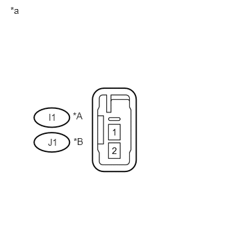
a.
U189934E02
0.719,2.052 1.01,2.219 0.292,0.167 10 false J1 1.104,2.042 1.323,2.208 0.219,0.167 10 false *B 0.729,1.677 1.021,1.844 0.292,0.167 10 false I1 1.094,1.656 1.313,1.823 0.219,0.167 10 false *A 0.156,0.073 0.333,0.24 0.177,0.167 10 false *a

Resistance check

i.

Measure the resistance according to the value(s) in the table below.

Standard Resistance:
Tester Connection Condition Specified Condition
I1-1 - I1-2 Always 3.2 to 4.8 Ω
J1-1 - J1-2 Always 3.2 to 4.8 Ω


Text in Illustration
*A for RH
*B for LH
*a Component without harness connected
(Front No. 1 Speaker Assembly)


OK

3.INSPECT REAR SPEAKER ASSEMBLY

NG

REPLACE FRONT NO. 1 SPEAKER ASSEMBLY

3.INSPECT REAR SPEAKER ASSEMBLY
a.
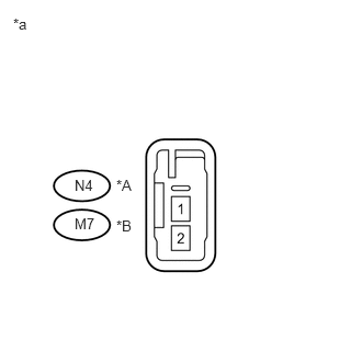
U189935E02
0.708,2.042 1,2.208 0.292,0.167 10 false M7 1.104,2.063 1.323,2.229 0.219,0.167 10 false *B 0.708,1.677 1,1.844 0.292,0.167 10 false N4 1.104,1.677 1.323,1.844 0.219,0.167 10 false *A 0.125,0.146 0.302,0.313 0.177,0.167 10 false *a

Resistance check

i.

Measure the resistance according to the value(s) in the table below.

Standard Resistance:
Tester Connection Condition Specified Condition
N4-1 - N4-2 Always 3.2 to 4.8 Ω
M7-1 - M7-2 Always 3.2 to 4.8 Ω


Text in Illustration
*A for RH
*B for LH
*a Component without harness connected
(Rear Speaker Assembly)


OK

4.INSPECT ROOF SPEAKER ASSEMBLY

NG

4.INSPECT ROOF SPEAKER ASSEMBLY
a.
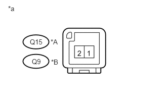
U189809E02
0.615,0.781 0.917,0.938 0.302,0.156 10 false Q15 1.042,0.781 1.25,0.938 0.208,0.156 10 false *A 0.167,0.094 0.354,0.25 0.188,0.156 10 false *a 0.656,1.188 0.885,1.344 0.229,0.156 10 false Q9 1.052,1.198 1.25,1.354 0.198,0.156 10 false *B

Resistance check

i.

Measure the resistance according to the value(s) in the table below.

Standard Resistance:
Tester Connection Condition Specified Condition
Q15-1 - Q15-2 Always 3.2 to 4.8 Ω
Q9-1 - Q9-2 Always 3.2 to 4.8 Ω


Text in Illustration
*A for RH
*B for LH
*a Component without harness connected
(Roof Speaker Assembly)


OK

5.REPLACE RADIO SETTING CONDENSER

NG

REPLACE ROOF SPEAKER ASSEMBLY

5.REPLACE RADIO SETTING CONDENSER
a.

Replace the radio setting condenser.


b.

Check if the same malfunction recurs.

Result:
Result Proceed to
Malfunction does not recur
(returns to normal)
A
Malfunction recurs B


A

END

B

PROCEED TO NEXT SUSPECTED AREA SHOWN IN PROBLEM SYMPTOMS TABLE