Home › Audio / Visual / Telematics › PARK ASSIST / MONITORING › TOYOTA PARKING ASSIST-SENSOR SYSTEM(for LHD) › from 2016.05
RM24M0E _56 Audio / Visual / Telematics _059590 PARK ASSIST / MONITORING _0292209 TOYOTA PARKING ASSIST-SENSOR SYSTEM(for LHD) J

PARK ASSIST / MONITORING  TOYOTA PARKING ASSIST-SENSOR SYSTEM(for LHD)  Back Sonar Sensor RH Circuit  


DESCRIPTION

An ultrasonic sensor consists of a sensor portion that transmits and receives ultrasonic waves and a preamplifier that amplifies them. The ultrasonic sensor outputs the ultrasonic waves and sends the received signals to the clearance warning ECU assembly.

WIRING DIAGRAM
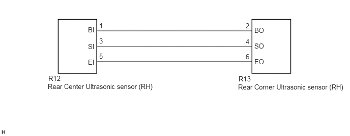
E256011E33
0.99,1.531 1.552,1.708 0.563,0.177 10 false R12 0.979,1.698 3.708,1.979 2.729,0.281 10 false Rear Center Ultrasonic sensor (RH) 4.885,1.542 5.24,1.969 0.354,0.427 10 false R13 4.875,1.708 7.146,1.99 2.271,0.281 10 false Rear Corner Ultrasonic sensor (RH) 1.802,0.531 1.948,0.708 0.146,0.177 10 false BI 1.802,0.875 1.948,1.052 0.146,0.177 10 false SI 1.802,1.198 1.948,1.375 0.146,0.177 10 false EI 2.031,0.448 2.125,0.625 0.094,0.177 10 false 1 2.031,0.76 2.125,0.938 0.094,0.177 10 false 3 2.031,1.073 2.125,1.25 0.094,0.177 10 false 5 5.031,0.448 5.125,0.625 0.094,0.177 10 false 2 5.031,0.771 5.125,0.948 0.094,0.177 10 false 4 5.031,1.083 5.125,1.26 0.094,0.177 10 false 6 5.208,0.542 5.427,0.719 0.219,0.177 10 false BO 5.208,0.865 5.427,1.042 0.219,0.177 10 false SO 5.208,1.188 5.427,1.365 0.219,0.177 10 false EO

PROCEDURE

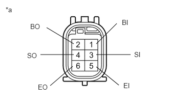
1.INSPECT REAR CENTER ULTRASONIC SENSOR (RH)
E270573E05
1.958,0.896 2.375,0.479 false 1.958,1.115 2.656,1.115 false 1.958,1.365 2.417,1.74 false 0.948,0.563 1.5,0.896 false 0.823,1.115 1.5,1.115 false 1.021,1.75 1.479,1.354 false 2.729,1.031 3.042,1.229 0.313,0.198 10 false SI 2.479,0.375 2.792,0.573 0.313,0.198 10 false BI 2.51,1.667 2.823,1.865 0.313,0.198 10 false EI 0.552,1.052 0.865,1.25 0.313,0.198 10 false SO 0.615,0.458 0.927,0.656 0.313,0.198 10 false BO 0.771,1.698 1.083,1.896 0.313,0.198 10 false EO 0.115,0.115 0.427,0.313 0.313,0.198 10 false *a

a.

b.

Measure the resistance according to the value(s) in the table below.

Standard Resistance:
Tester Connection Condition Specified Condition
1 (BI) - 5 (EI) Always 10 kΩ or higher
1 (BI) - 2 (BO) Always 10 kΩ or higher
3 (SI) - 4 (SO) Always Below 1 Ω
5 (EI) - 6 (EO) Always Below 1 Ω


Text in Illustration
*a Component without harness connected
(Rear Center Ultrasonic Sensor (RH))


OK

2.CHECK HARNESS AND CONNECTOR (REAR CENTER ULTRASONIC SENSOR (RH) - REAR CORNER ULTRASONIC SENSOR (RH))

NG

2.CHECK HARNESS AND CONNECTOR (REAR CENTER ULTRASONIC SENSOR (RH) - REAR CORNER ULTRASONIC SENSOR (RH))
a.

Disconnect the R12 rear center ultrasonic sensor (RH) connector and R13 rear corner ultrasonic sensor (RH) connector.


b.

Measure the resistance according to the value(s) in the table below.

Standard Resistance:
Tester Connection Condition Specified Condition
R12-1 (BI) - R13-2 (BO) Always Below 1 Ω
R12-3 (SI) - R13-4 (SO) Always Below 1 Ω
R12-5 (EI) - R13-6 (EO) Always Below 1 Ω
R12-1 (BI) - Body ground Always 10 kΩ or higher
R12-3 (SI) - Body ground Always 10 kΩ or higher
R12-5 (EI) - Body ground Always 10 kΩ or higher


OK

NG

REPAIR OR REPLACE HARNESS OR CONNECTOR