WINDOW / GLASS POWER WINDOW CONTROL SYSTEM B1206 P/W Master Switch Communication Stop
DESCRIPTION
This DTC is output when communication between the multiplex network master switch and main body ECU stops for more than 10 seconds.
| DTC No. | DTC Detection Condition | Trouble Area |
|---|---|---|
| B1206 | No communication between multiplex network master switch and main body ECU for more than 10 seconds | ·
Multiplex network master switch ·
Main body ECU ·
Wire harness |
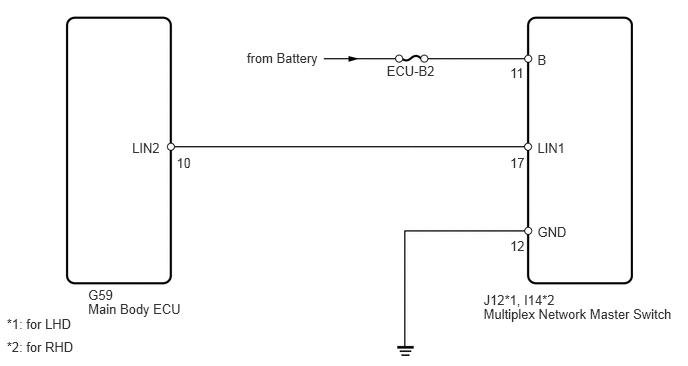
WIRING DIAGRAM
PROCEDURE
Delete the DTC (see page Vehicle Interior>WINDOW / GLASS>POWER WINDOW CONTROL SYSTEM>DTC CHECK / CLEAR).
Check for DTCs again.
| Result | Proceed to |
|---|---|
| B1206 is output | A |
| B1206 is not output | B |
A
B
Remove the ECU-B2 fuse from the engine room No. 2 relay block.
Measure the resistance of the fuse.
- Standard resistance:
Below 1 Ω
OK
NG
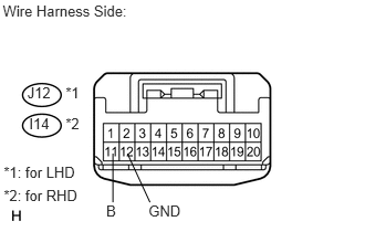
Disconnect the J12*1 or I14*2 switch connector.
Measure the voltage and resistance of the wire harness side connector.
- Standard voltage:
for LHD Tester Connection Specified Condition J12-11 (B) - Body ground 10 to 14 V
for RHD Tester Connection Specified Condition I14-11 (B) - Body ground 10 to 14 V
- Standard resistance:
for LHD Tester Connection Specified Condition J12-12 (GND) - Body ground Below 1 Ω
for RHD Tester Connection Specified Condition I14-12 (GND) - Body ground Below 1 Ω
OK
NG
Disconnect the G59 ECU connector.
Disconnect the J12*1 or I14*2 switch connector.
Measure the resistance of the wire harness side connectors.
- Standard resistance:
for LHD Tester Connection Specified Condition G59-10 (LIN2) - J12-17 (LIN1) Below 1 Ω G59-10 (LIN2) or J12-17 (LIN1) - Body ground 10 kΩ or higher
for RHD Tester Connection Specified Condition G59-10 (LIN2) - I14-17 (LIN1) Below 1 Ω G59-10 (LIN2) or I14-17 (LIN1) - Body ground 10 kΩ or higher
OK
NG
Temporarily replace the master switch with a new or normally functioning one.
NEXT
Delete the DTC (see page Vehicle Interior>WINDOW / GLASS>POWER WINDOW CONTROL SYSTEM>DTC CHECK / CLEAR).
Check for DTCs again.
| Result | Proceed to |
|---|---|
| B1206 is not output | A |
| B1206 is output | B |
A
B