Home › Vehicle Interior › WINDOW / GLASS › POWER WINDOW CONTROL SYSTEM › from 2014.09
RM24M0E _58 Vehicle Interior _059592 WINDOW / GLASS _0292216 POWER WINDOW CONTROL SYSTEM J

WINDOW / GLASS  POWER WINDOW CONTROL SYSTEM  Driver Side Power Window Auto Up / Down Function does not Operate with Power Window Master Switch  


DESCRIPTION

If the manual UP / DOWN function can be performed but the AUTO UP / DOWN function cannot, then the fail-safe may be functioning.

If the power window initialization (see page Vehicle Interior>WINDOW / GLASS>POWER WINDOW CONTROL SYSTEM>INITIALIZATION) has not been performed, the AUTO UP / DOWN function will not operate.

WIRING DIAGRAM
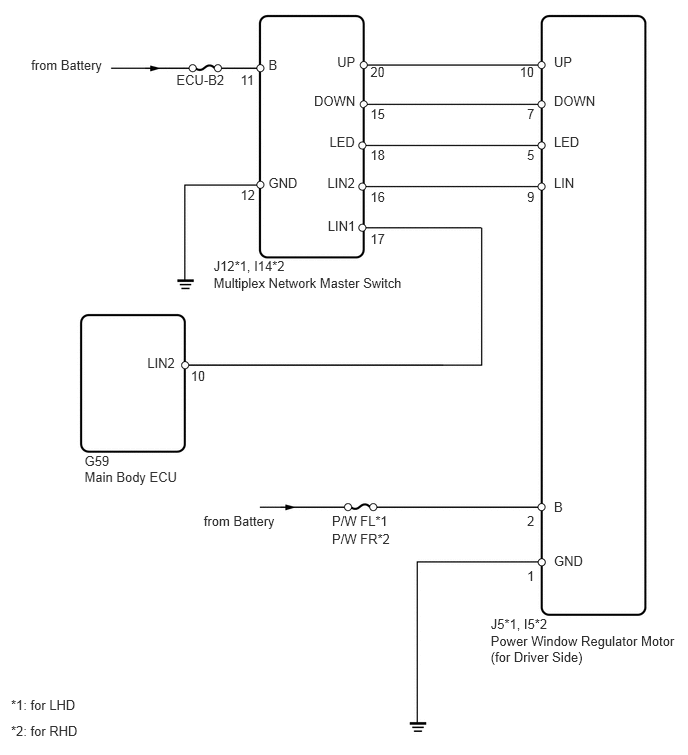
B142472E06
0.88,4.718 1.925,4.882 1.045,0.164 10 G59 0.88,4.889 1.925,5.053 1.045,0.164 10 Main Body ECU 1.837,0.755 2.429,0.919 0.592,0.164 10 ECU-B2 2.225,2.685 4.264,2.849 2.039,0.164 10 J12*1, I14*2 2.225,2.867 4.264,3.031 2.039,0.164 10 Multiplex Network Master Switch 5.111,6.589 7.150,6.753 2.039,0.164 10 Power Window Regulator Motor 5.111,6.421 7.150,6.585 2.039,0.164 10 J5*1, I5*2 5.111,6.758 7.150,6.922 2.039,0.164 10 (for Driver Side) 3.458,5.529 4.192,5.693 0.734,0.164 10 P/W FR*2 3.458,5.347 4.192,5.511 0.734,0.164 10 P/W FL*1 5.49,5.347 5.591,5.511 0.101,0.164 10 2 5.49,1.971 5.591,2.135 0.101,0.164 10 9 5.49,1.536 5.591,1.700 0.101,0.164 10 5 5.49,1.102 5.591,1.266 0.101,0.164 10 7 5.413,0.668 5.653,0.832 0.240,0.164 10 10 3.858,0.668 4.098,0.832 0.240,0.164 10 20 2.505,0.755 2.697,0.919 0.193,0.164 10 11 2.505,1.946 2.701,2.110 0.196,0.164 10 12 3.858,1.102 4.098,1.266 0.240,0.164 10 15 3.858,1.536 4.098,1.700 0.240,0.164 10 18 3.858,1.971 4.098,2.135 0.240,0.164 10 16 3.858,2.411 4.098,2.575 0.240,0.164 10 17 5.49,5.922 5.591,6.086 0.101,0.164 10 1 0.114,7.259 1.755,7.423 1.641,0.164 10 *1: for LHD 0.114,7.529 1.755,7.693 1.641,0.164 10 *2: for RHD 2.796,1.818 3.207,1.982 0.411,0.164 10 GND 2.796,0.599 3.207,0.763 0.411,0.164 10 B 5.77,1.818 6.016,1.982 0.247,0.164 10 LIN 3.512,0.562 3.732,0.726 0.220,0.164 10 UP 3.271,0.968 3.730,1.132 0.458,0.164 10 DOWN 3.432,1.401 3.731,1.565 0.300,0.164 10 LED 3.41,1.818 3.731,1.982 0.321,0.164 10 LIN2 3.414,2.267 3.731,2.431 0.317,0.164 10 LIN1 5.77,5.201 6.154,5.365 0.384,0.164 10 B 5.77,5.764 6.154,5.928 0.384,0.164 10 GND 1.534,3.696 1.875,3.860 0.341,0.164 10 LIN2 5.77,0.562 5.990,0.726 0.220,0.164 10 UP 5.77,0.968 6.228,1.132 0.458,0.164 10 DOWN 5.77,1.401 6.069,1.565 0.300,0.164 10 LED 0.324,0.598 1.113,0.762 0.789,0.164 10 from Battery 2.122,5.347 2.912,5.511 0.789,0.164 10 from Battery 1.987,3.838 2.226,4.002 0.240,0.164 10 10

PROCEDURE

1.READ VALUE USING INTELLIGENT TESTER (LIN COMMUNICATION)
a.

Connect the intelligent tester to the DLC3.


b.

Turn the ignition switch on (IG) and turn the tester ON.


c.

Select the following menu items: Body / Body ECU / Data List.


d.

Read the display on the tester.

Main body ECU
Item Measurement Item / Display (Range) Normal Condition Diagnostic Note
Communication D-Door Motor Connection status between power window regulator motor (driver side) and main body ECU / OK or STOP OK: Connection
Stop: No connection
-

OK:

OK is displayed on the intelligent tester screen.


OK

2.READ VALUE USING INTELLIGENT TESTER (POWER WINDOW SWITCH)

NG

GO TO DTC B2325

2.READ VALUE USING INTELLIGENT TESTER (POWER WINDOW SWITCH)
a.

Connect the intelligent tester to the DLC3.


b.

Turn the ignition switch on (IG) and turn the tester ON.


c.

Select the following menu items: Body / Master Switch / Data List.


d.

Read the display on the tester.

Multiplex network master switch
Item Measurement Item / Display (Range) Normal Condition Diagnostic Note
D Door P/W Auto SW Driver side power window AUTO UP / DOWN switch signal / ON or OFF ON: Driver side power window switch operates (AUTO operation)
OFF: Driver side power window switch does not operate
-

OK:

ON is displayed on the intelligent tester screen during AUTO operation.


OK

3.READ VALUE USING INTELLIGENT TESTER (POWER WINDOW SWITCH)

NG

REPLACE MULTIPLEX NETWORK MASTER SWITCH ASSEMBLY

3.READ VALUE USING INTELLIGENT TESTER (POWER WINDOW SWITCH)
a.

Connect the intelligent tester to the DLC3.


b.

Turn the ignition switch on (IG) and turn the tester ON.


c.

Select the following menu items: Body / D-Door Motor / Data List.


d.

Read the display on the tester.

Driver side power window regulator motor (Power window ECU)
Item Measurement Item / Display (Range) Normal Condition Diagnostic Note
D Door P/W Auto SW Driver side power window AUTO UP / DOWN switch signal / ON or OFF ON: Driver side power window switch operates (AUTO operation)
OFF: Driver side power window switch does not operate
-

OK:

ON is displayed on the intelligent tester screen during AUTO operation.


OK

REPLACE POWER WINDOW REGULATOR MOTOR ASSEMBLY (for Driver Side)

NG

REPAIR OR REPLACE HARNESS OR CONNECTOR (MASTER SWITCH - MOTOR)