WINDOW / GLASS POWER WINDOW CONTROL SYSTEM B2325 LIN Communication Bus Malfunction
DESCRIPTION
The main body ECU detects door bus communication errors. This DTC is output when a communication error is detected 3 times consecutively.
| DTC No. | DTC Detection Condition | Trouble Area |
|---|---|---|
| B2325 | Main body ECU detects door bus communication error (LIN communication malfunction) 3 times consecutively | ·
Main body ECU ·
Wire harness |
WIRING DIAGRAM
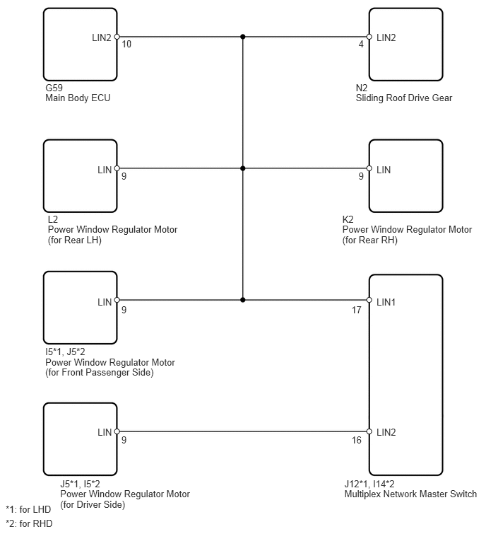
PROCEDURE
Delete the DTC (see page Vehicle Interior>WINDOW / GLASS>POWER WINDOW CONTROL SYSTEM>DTC CHECK / CLEAR).
Check for DTCs again.
| Result | Proceed to |
|---|---|
| B2325 is output | A |
| B2325 is not output | B |
A
B
Disconnect the J12*1 or I14*2 switch connector.
Disconnect the J5*1 or I5*2 motor connector.
Measure the resistance of the wire harness side connectors.
- Standard resistance:
for LHD Tester Connection Specified Condition J12-16 (LIN2) - J5-9 (LIN) Below 1 Ω J12-16 (LIN2) or J5-9 (LIN) - Body ground 10 kΩ or higher
for RHD Tester Connection Specified Condition I14-16 (LIN2) - I5-9 (LIN) Below 1 Ω I14-16 (LIN2) or I5-9 (LIN) - Body ground 10 kΩ or higher
OK
NG
Main body ECU - Multiplex network master switch:
Disconnect the G59 ECU connector.
Disconnect the J12*1 or I14*2 switch connector.
Measure the resistance of the wire harness side connectors.
- Standard resistance:
for LHD Tester Connection Specified Condition G59-10 (LIN2) - J12-17 (LIN1) Below 1 Ω G59-10 (LIN2) or J12-17 (LIN1) - Body ground 10 kΩ or higher
for RHD Tester Connection Specified Condition G59-10 (LIN2) - I14-17 (LIN1) Below 1 Ω G59-10 (LIN2) or I14-17 (LIN1) - Body ground 10 kΩ or higher
Main body ECU - Power window regulator motor (for front passenger side):
Disconnect the G59 ECU connector.
Disconnect the I5*1 or J5*2 motor connector.
Measure the resistance of the wire harness side connectors.
- Standard resistance:
for LHD Tester Connection Specified Condition G59-10 (LIN2) - I5-9 (LIN) Below 1 Ω G59-10 (LIN2) or I5-9 (LIN) - Body ground 10 kΩ or higher
for RHD Tester Connection Specified Condition G59-10 (LIN2) - J5-9 (LIN) Below 1 Ω G59-10 (LIN2) or J5-9 (LIN) - Body ground 10 kΩ or higher
Main body ECU - Power window regulator motor (for rear LH):
Disconnect the G59 ECU connector.
Disconnect the L2 motor connector.
Measure the resistance of the wire harness side connectors.
- Standard resistance:
Tester Connection Specified Condition G59-10 (LIN2) - L2-9 (LIN) Below 1 Ω G59-10 (LIN2) or L2-9 (LIN) - Body ground 10 kΩ or higher
Main body ECU - Power window regulator motor (for rear RH):
Disconnect the G59 ECU connector.
Disconnect the K2 motor connector.
Measure the resistance of the wire harness side connectors.
- Standard resistance:
Tester Connection Specified Condition G59-10 (LIN2) - K2-9 (LIN) Below 1 Ω G59-10 (LIN2) or K2-9 (LIN) - Body ground 10 kΩ or higher
Main body ECU - Sliding roof drive gear:
- HINT:
-
w/ Sliding roof
Disconnect the G59 ECU connector.
Disconnect the N2 sliding roof connector.
Measure the resistance of the wire harness side connectors.
- Standard resistance:
Tester Connection Specified Condition G59-10 (LIN2) - N2-4 (LIN2) Below 1 Ω G59-10 (LIN2) or N2-4 (LIN2) - Body ground 10 kΩ or higher
Main body ECU - Body ground:
Disconnect the G59 ECU connector.
Measure the resistance of the wire harness side connector.
- Standard resistance:
Tester Connection Specified Condition G59-10 (LIN2) - Body ground 10 kΩ or higher
OK
NG
| Vehicle Equipment | Proceed to |
|---|---|
| w/ Sliding roof | A |
| w/o Sliding roof | B |
A
B
Disconnect the N2 sliding roof connector.
Check for DTCs again.
| Result | Proceed to |
|---|---|
| B2325 is output | A |
| B2325 is not output | B |
A
B
Disconnect the K2 motor connector.
Check for DTCs again.
| Result | Proceed to |
|---|---|
| B2325 is output | A |
| B2325 is not output | B |
A
B
Disconnect the L2 motor connector.
Check for DTCs again.
| Result | Proceed to |
|---|---|
| B2325 is output | A |
| B2325 is not output | B |
A
B
Disconnect the I5*1 or J5*2 motor connector.
- HINT:
-
*1: for LHD
-
*2: for RHD
Check for DTCs again.
| Result | Proceed to |
|---|---|
| B2325 is output | A |
| B2325 is not output | B |
A
B
Disconnect the J5*1 or I5*2 motor connector.
- HINT:
-
*1: for LHD
-
*2: for RHD
Check for DTCs again.
| Result | Proceed to |
|---|---|
| B2325 is output | A |
| B2325 is not output | B |
A
B
Disconnect the J12*1 or I14*2 switch connector.
- HINT:
-
*1: for LHD
-
*2: for RHD
Check for DTCs again.
| Result | Proceed to |
|---|---|
| B2325 is output | A |
| B2325 is not output | B |
A
B
Temporarily replace the sliding roof drive gear with a new or normally functioning one.
NEXT
Check for DTCs again.
| Result | Proceed to |
|---|---|
| B2325 is output | A |
| B2325 is not output | B |
A
B
Temporarily replace the power window regulator motor (for rear RH) with a new or normally functioning one.
NEXT
Check for DTCs again.
| Result | Proceed to |
|---|---|
| B2325 is output | A |
| B2325 is not output | B |
A
B
Temporarily replace the power window regulator motor (for rear LH) with a new or normally functioning one.
NEXT
Check for DTCs again.
| Result | Proceed to |
|---|---|
| B2325 is output | A |
| B2325 is not output | B |
A
B
Temporarily replace the power window regulator motor (for front passenger side) with a new or normally functioning one.
NEXT
Check for DTCs again.
| Result | Proceed to |
|---|---|
| B2325 is output | A |
| B2325 is not output | B |
A
B
Temporarily replace the power window regulator motor (for driver side) with a new or normally functioning one.
NEXT
Check for DTCs again.
| Result | Proceed to |
|---|---|
| B2325 is output | A |
| B2325 is not output | B |
A
B
Temporarily replace the multiplex network master switch with a new or normally functioning one.
NEXT
Check for DTCs again.
| Result | Proceed to |
|---|---|
| B2325 is output | A |
| B2325 is not output | B |
A
B