Home › Power Source / Network › CAN COMMUNICATION › CAN COMMUNICATION SYSTEM › 2013.04–2016.05
RM24M0E _57 Power Source / Network _059598 CAN COMMUNICATION _0292257 CAN COMMUNICATION SYSTEM J

CAN COMMUNICATION  CAN COMMUNICATION SYSTEM  CAN Main Wire for Disconnection (RHD Models)  


DESCRIPTION

There may be an open circuit in the CAN main wire and/or the DLC3 branch wire when the resistance between terminals 6 (CANH) and 14 (CANL) of the DLC3 is 70 Ω or more.

Symptom Trouble Area
Resistance between terminals 6 (CANH) and 14 (CANL) of DLC3 is 70 Ω or more.
·

CAN main wire and connector

·

No. 2 CAN junction connector LH

·

No. 2 junction connector

·

No. 4 junction connector

·

No. 5 junction connector

·

ECM

·

Combination meter ECU


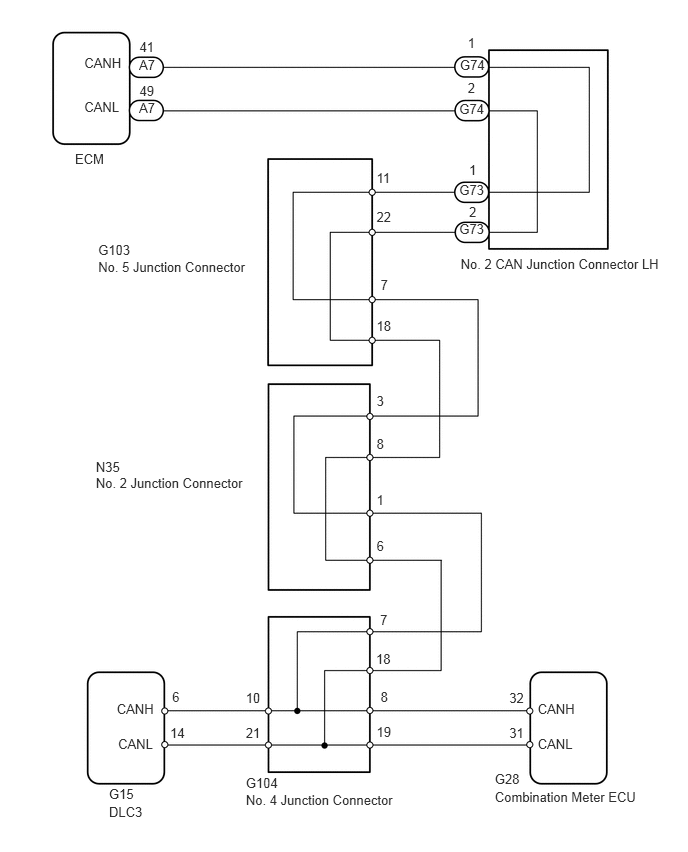
WIRING DIAGRAM

C286243E01
0.878,0.571 1.333,0.746 0.456,0.175 10 CANH 1.448,0.589 1.671,0.763 0.223,0.175 10 A7 4.791,0.589 5.095,0.763 0.304,0.175 10 G74 4.784,1.055 5.088,1.229 0.304,0.175 10 G74 4.784,1.898 5.088,2.073 0.304,0.175 10 G73 4.784,2.306 5.088,2.480 0.304,0.175 10 G73 1.453,0.406 1.676,0.581 0.223,0.175 10 41 3.922,1.775 4.144,1.950 0.223,0.175 10 11 3.964,2.889 4.186,3.063 0.223,0.175 10 7 3.922,4.099 4.145,4.274 0.223,0.175 10 3 3.922,5.122 4.145,5.297 0.223,0.175 10 1 3.922,5.606 4.145,5.781 0.223,0.175 10 6 3.917,6.782 4.140,6.957 0.223,0.175 10 18 2.56,7.19 2.783,7.365 0.223,0.175 10 10 2.56,7.557 2.783,7.731 0.223,0.175 10 21 1.772,7.557 1.994,7.731 0.223,0.175 10 14 3.922,7.543 4.145,7.717 0.223,0.175 10 19 5.305,7.19 5.528,7.365 0.223,0.175 10 32 5.305,7.557 5.528,7.731 0.223,0.175 10 31 3.959,6.379 4.182,6.554 0.223,0.175 10 7 3.964,7.176 4.187,7.351 0.223,0.175 10 8 1.793,7.176 2.016,7.351 0.223,0.175 10 6 3.922,4.541 4.145,4.716 0.223,0.175 10 8 3.922,2.176 4.144,2.351 0.223,0.175 10 22 3.922,3.31 4.144,3.484 0.223,0.175 10 18 4.872,0.369 5.047,0.544 0.175,0.175 10 1 4.872,0.837 5.047,1.012 0.175,0.175 10 2 4.886,1.683 5.061,1.858 0.175,0.175 10 1 4.886,2.124 5.061,2.298 0.175,0.175 10 2 1.453,0.865 1.676,1.040 0.223,0.175 10 49 1.448,1.038 1.671,1.213 0.223,0.175 10 A7 0.878,1.028 1.333,1.202 0.456,0.175 10 CANL 1.216,7.307 1.672,7.481 0.456,0.175 10 CANH 1.23,7.665 1.686,7.840 0.456,0.175 10 CANL 1.135,8.191 1.591,8.365 0.456,0.175 10 G15 1.135,8.37 1.591,8.545 0.456,0.175 10 DLC3 2.561,8.073 3.016,8.248 0.456,0.175 10 G104 2.561,8.253 4.570,8.456 2.010,0.203 10 No. 4 Junction Connector 5.154,8.036 5.610,8.210 0.456,0.175 10 G28 5.154,8.215 7.030,8.419 1.876,0.203 10 Combination Meter ECU 1.023,2.519 1.479,2.694 0.456,0.175 10 G103 1.023,2.699 2.709,2.902 1.686,0.203 10 No. 5 Junction Connector 4.798,2.664 6.986,2.868 2.188,0.203 10 No. 2 CAN Junction Connector LH 0.998,4.779 1.454,4.954 0.456,0.175 10 N35 0.998,4.948 3.008,5.151 2.010,0.203 10 No. 2 Junction Connector 5.601,7.307 6.056,7.481 0.456,0.175 10 CANH 5.601,7.665 6.056,7.840 0.456,0.175 10 CANL 0.781,1.574 1.127,1.749 0.346,0.175 10 ECM

CAUTION / NOTICE / HINT

NOTICE:

Turn the engine switch off before measuring the resistances of the main wire and the branch wire.


HINT:

Operating the engine switch, any switches or any doors triggers related ECU and sensor communication with the CAN, which causes resistance variation.


PROCEDURE
1.CHECK DLC3
a.
U190031E02
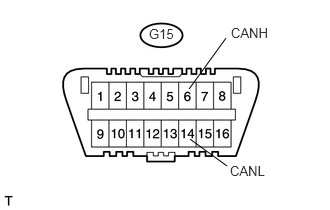
2.354,0.396 1.969,0.927 false 1.979,1.448 2.365,1.729 false 1.552,0.271 1.833,0.448 0.281,0.177 10 false G15 2.406,0.26 2.844,0.438 0.438,0.177 10 false CANH 2.396,1.698 2.833,1.875 0.438,0.177 10 false CANL

Measure the resistance of the DLC3.

Result
Tester Connection Condition Measured Resistance Proceed to
G15-6 (CANH) - G15-14 (CANL) Engine switch off 108 to 132 Ω A
G15-6 (CANH) - G15-14 (CANL) Engine switch off 133 Ω or more B

NOTICE:

When the measured value is 133 Ω or more and a CAN communication system diagnostic trouble code is output, there may be a fault besides disconnection of the DLC3 branch wire. For that reason, troubleshooting should be performed again from "HOW TO PROCEED WITH TROUBLESHOOTING" (see page Power Source / Network>CAN COMMUNICATION>CAN COMMUNICATION SYSTEM>HOW TO PROCEED WITH TROUBLESHOOTING) after repairing the trouble area.


A

2.CHECK FOR OPEN IN CAN MAIN WIRES (NO. 5 JUNCTION CONNECTOR - NO. 2 CAN JUNCTION CONNECTOR LH)

B

REPAIR OR REPLACE CAN BRANCH WIRE CONNECTED TO DLC3 (CANH, CANL)

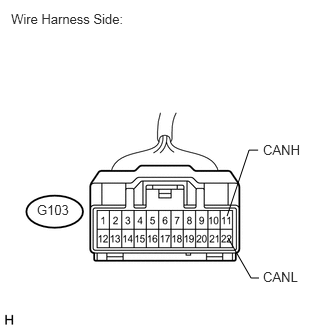
2.CHECK FOR OPEN IN CAN MAIN WIRES (NO. 5 JUNCTION CONNECTOR - NO. 2 CAN JUNCTION CONNECTOR LH)
a.
U189520E02
2.365,2.25 2.594,1.563 2.594,1.563 2.688,1.563 false 2.375,2.479 2.615,2.896 2.615,2.896 2.698,2.896 false 0.385,2.104 0.76,2.271 0.375,0.167 10 false G103 0.115,0.115 2.573,0.5 2.458,0.385 10 false Wire Harness Side: 2.74,1.479 3.229,1.677 0.49,0.198 10 false CANH 2.74,2.802 3.229,3 0.49,0.198 10 false CANL

Disconnect the G103 No. 5 junction connector.

b.

Measure the resistance of the wire harness side connector.

Standard resistance:
Tester Connection Condition Specified Condition
G103-11 (CANH) - G103-22 (CANL) Engine switch off 108 to 132 Ω


OK

3.CHECK FOR OPEN IN CAN MAIN WIRES (NO. 5 JUNCTION CONNECTOR - NO. 2 JUNCTION CONNECTOR)

NG

9.CHECK FOR OPEN IN CAN MAIN WIRES (NO. 2 CAN JUNCTION CONNECTOR LH - NO. 5 JUNCTION CONNECTOR)
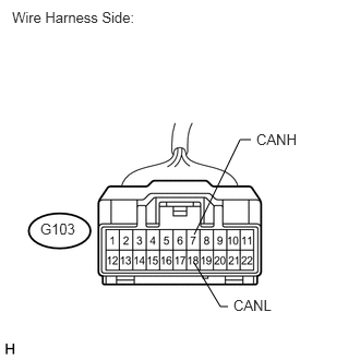
3.CHECK FOR OPEN IN CAN MAIN WIRES (NO. 5 JUNCTION CONNECTOR - NO. 2 JUNCTION CONNECTOR)
a.
U189522E02
1.854,2.24 2.292,1.333 2.292,1.333 2.396,1.333 false 1.854,2.51 2.104,2.927 2.104,2.927 2.177,2.927 false 0.385,2.104 0.76,2.271 0.375,0.167 10 false G103 0.115,0.083 2.573,0.469 2.458,0.385 10 false Wire Harness Side: 2.448,1.25 2.938,1.448 0.49,0.198 10 false CANH 2.229,2.833 2.719,3.031 0.49,0.198 10 false CANL

Measure the resistance of the wire harness side connector.

Standard resistance:
Tester Connection Condition Specified Condition
G103-7 (CANH) - G103-18 (CANL) Engine switch off 108 to 132 Ω


OK

REPLACE NO. 5 JUNCTION CONNECTOR

NG

4.CHECK FOR OPEN IN CAN MAIN WIRES (NO. 2 JUNCTION CONNECTOR - NO. 5 JUNCTION CONNECTOR)
a.

Reconnect the G103 No. 5 junction connector.


b.
U189082E02
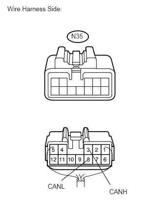
1.854,3.427 1.313,3.854 false 1.917,3.219 2.354,3.948 false 0.156,0.104 1.458,0.281 1.302,0.177 10 false Wire Harness Side: 1.521,0.688 1.844,0.854 0.323,0.167 10 false N35 1.021,3.896 1.458,4.052 0.438,0.156 10 false CANL 2.333,4.01 2.771,4.167 0.438,0.156 10 false CANH

Disconnect the N35 No. 2 junction connector.

c.

Measure the resistance of the wire harness side connector.

Standard resistance:
Tester Connection Condition Specified Condition
N35-3 (CANH) - N35-8 (CANL) Engine switch off 108 to 132 Ω


OK

5.CHECK FOR OPEN IN CAN MAIN WIRES (NO. 2 JUNCTION CONNECTOR - NO. 4 JUNCTION CONNECTOR)

NG

REPAIR OR REPLACE CAN MAIN WIRE OR CONNECTOR (NO. 2 JUNCTION CONNECTOR - NO. 5 JUNCTION CONNECTOR)

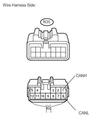
5.CHECK FOR OPEN IN CAN MAIN WIRES (NO. 2 JUNCTION CONNECTOR - NO. 4 JUNCTION CONNECTOR)
a.
U189086E02
2.25,3.427 2.677,3.906 false 2.25,3.146 2.656,2.688 false 0.104,0.094 1.406,0.271 1.302,0.177 10 false Wire Harness Side: 1.531,0.688 1.854,0.854 0.323,0.167 10 false N35 2.792,3.917 3.229,4.073 0.438,0.156 10 false CANL 2.688,2.594 3.125,2.75 0.438,0.156 10 false CANH

Measure the resistance of the wire harness side connector.

Standard resistance:
Tester Connection Condition Specified Condition
N35-1 (CANH) - N35-6 (CANL) Engine switch off 108 to 132 Ω


OK

REPLACE NO. 2 JUNCTION CONNECTOR

NG

6.CHECK FOR OPEN IN CAN MAIN WIRES (NO. 4 JUNCTION CONNECTOR - NO. 2 JUNCTION CONNECTOR)
a.

Reconnect the N35 No. 2 junction connector.


b.
U189526E02
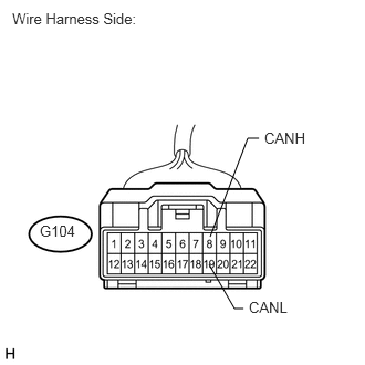
1.844,2.24 2.198,1.313 2.198,1.313 2.292,1.313 false 1.854,2.521 2.104,2.938 2.104,2.938 2.177,2.938 false 0.385,2.104 0.76,2.271 0.375,0.167 10 false G104 0.115,0.104 2.573,0.49 2.458,0.385 10 false Wire Harness Side: 2.354,1.208 2.844,1.406 0.49,0.198 10 false CANH 2.229,2.865 2.719,3.063 0.49,0.198 10 false CANL

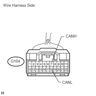
Disconnect the G104 No. 4 junction connector.

c.

Measure the resistance of the wire harness side connector.

Standard resistance:
Tester Connection Condition Specified Condition
G104-7 (CANH) - G104-18 (CANL) Engine switch off 108 to 132 Ω


OK

7.CHECK FOR OPEN IN CAN MAIN WIRES (NO. 4 JUNCTION CONNECTOR - COMBINATION METER ECU)

NG

REPAIR OR REPLACE CAN MAIN WIRE OR CONNECTOR (NO. 4 JUNCTION CONNECTOR - NO. 2 JUNCTION CONNECTOR)

7.CHECK FOR OPEN IN CAN MAIN WIRES (NO. 4 JUNCTION CONNECTOR - COMBINATION METER ECU)
a.
U189525E02
1.979,2.229 2.333,1.302 2.333,1.302 2.438,1.302 false 1.969,2.49 2.208,2.906 2.208,2.906 2.292,2.906 false 0.375,2.094 0.75,2.26 0.375,0.167 10 false G104 0.115,0.094 2.573,0.479 2.458,0.385 10 false Wire Harness Side: 2.49,1.219 2.979,1.417 0.49,0.198 10 false CANH 2.344,2.813 2.833,3.01 0.49,0.198 10 false CANL

Measure the resistance of the wire harness side connector.

Standard resistance:
Tester Connection Condition Specified Condition
G104-8 (CANH) - G104-19 (CANL) Engine switch off 108 to 132 Ω


OK

REPLACE No. 4 JUNCTION CONNECTOR

NG

8.CHECK FOR OPEN IN CAN MAIN WIRES (COMBINATION METER ECU - NO. 2 JUNCTION CONNECTOR)
a.

Reconnect the G104 No. 4 junction connector.


b.
U188994E01
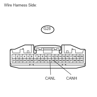
0.144,0.099 1.429,0.283 1.286,0.184 10 Wire Harness Side: 1.54,0.929 1.849,1.126 0.309,0.198 10 G28 1.598,2.689 2.031,2.859 0.433,0.170 10 CANL 2.345,2.689 2.779,2.859 0.434,0.170 10 CANH 1.769,2.138 1.794,2.651 false 1.896,2.137 2.521,2.645 false

Disconnect the G28 combination meter ECU connector.


c.

Measure the resistance of the wire harness side connector.

Standard resistance:
Tester Connection Condition Specified Condition
G28-32 (CANH) - G28-31 (CANL) Engine switch off 108 to 132 Ω


OK

REPLACE COMBINATION METER ASSEMBLY (COMBINATION METER ECU)

NG

REPAIR OR REPLACE CAN MAIN WIRE CONNECTED TO COMBINATION METER ASSEMBLY (COMBINATION METER ECU - NO. 4 JUNCTION CONNECTOR)

9.CHECK FOR OPEN IN CAN MAIN WIRES (NO. 2 CAN JUNCTION CONNECTOR LH - NO. 5 JUNCTION CONNECTOR)
a.

Reconnect the G103 No. 5 junction connector.

b.
U189683E02
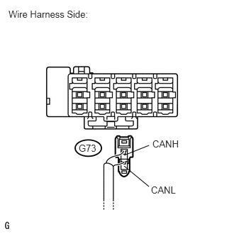
1.823,2.438 2.188,2.74 false 1.823,2.281 2.188,2.135 false 2.219,2.708 2.635,2.875 0.417,0.167 10 false CANL 2.24,2.031 2.656,2.198 0.417,0.167 10 false CANH 1.156,2.094 1.438,2.24 0.281,0.146 10 false G73 0.125,0.125 1.406,0.302 1.281,0.177 10 false Wire Harness Side:

Disconnect the G73 No. 2 CAN junction connector LH connector.

c.

Measure the resistance of the wire harness side connector.

Standard resistance:
Tester Connection Condition Specified Condition
G73-1 (CANH) - G73-2 (CANL) Engine switch off 108 to 132 Ω


OK

10.CHECK FOR OPEN IN CAN MAIN WIRES (NO. 2 CAN JUNCTION CONNECTOR LH - ECM)

NG

REPAIR OR REPLACE CAN MAIN WIRE OR CONNECTOR (NO. 2 CAN JUNCTION CONNECTOR LH - NO. 5 JUNCTION CONNECTOR)

10.CHECK FOR OPEN IN CAN MAIN WIRES (NO. 2 CAN JUNCTION CONNECTOR LH - ECM)
a.
U189249E02
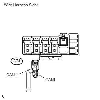
0.99,2.396 0.667,2.542 false 1.135,2.469 1.521,2.677 false 0.438,2.01 0.729,2.156 0.292,0.146 10 false G74 0.219,2.49 0.646,2.635 0.427,0.146 10 false CANH 1.563,2.656 1.99,2.802 0.427,0.146 10 false CANL 0.135,0.083 1.531,0.292 1.396,0.208 10 false Wire Harness Side:

Disconnect the G74 No. 2 CAN junction connector LH connector.


b.

Measure the resistance of the wire harness side connector.

Standard resistance:
Tester Connection Condition Specified Condition
G74-1 (CANH) - G74-2 (CANL) Engine switch off 108 to 132 Ω


OK

REPLACE NO. 2 CAN JUNCTION CONNECTOR LH

NG

11.CHECK FOR OPEN IN CAN MAIN WIRES (ECM - NO. 2 CAN JUNCTION CONNECTOR LH)
a.

Reconnect the G74 No. 2 CAN junction connector LH connector.


b.
U189000E02
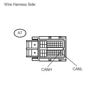
2.24,1.865 1.74,2.448 false 2.24,1.938 2.813,2.417 false 0.156,0.073 1.479,0.24 1.323,0.167 10 false Wire Harness Side: 0.646,1.115 0.854,1.271 0.208,0.156 10 false A7 2.656,2.438 3.198,2.604 0.542,0.167 10 false CANL 1.51,2.458 2.063,2.625 0.552,0.167 10 false CANH

Disconnect the A7 ECM connector.


c.

Measure the resistance of the wire harness side connector.

Standard resistance:
Tester Connection Condition Specified Condition
A7-41 (CANH) - A7-49 (CANL) Engine switch off 108 to 132 Ω


OK

REPLACE ECM

NG

REPAIR OR REPLACE CAN MAIN WIRE CONNECTED TO ECM (ECM - NO. 2 CAN JUNCTION CONNECTOR LH)