TERMINALS OF ECU
System information · Vehicles built from Nov 2010
Versions by build date: Jul 2007 – Oct 2010 from Nov 2010
| CHECK MAIN BODY ECU |
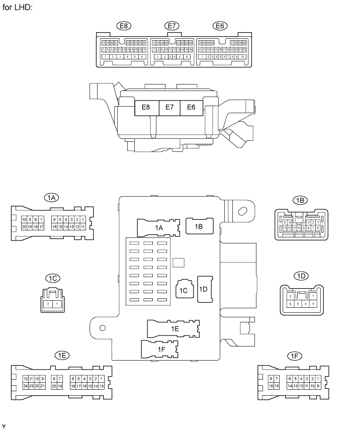

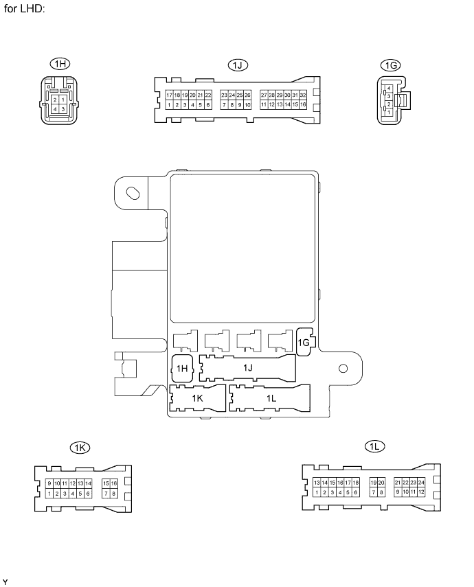
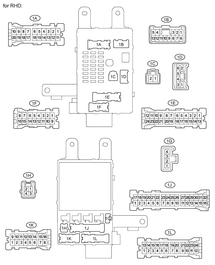
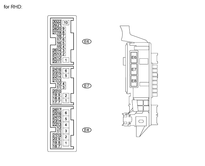
Disconnect the 1B, 1E, 1L and 1H main body ECU connectors.
Measure the voltages and resistances of the wire harness side connectors.
Terminal No. (Symbol)
Wiring Color
Terminal Description
Condition
Specified Condition
1H-2 (GND1) - Body ground
W-B - Body ground
Ground
Always
Below 1 Ω
1B-4 (BECU) - Body ground*1
W-R - Body ground
Power source circuit (From battery)
Always
11 to 14 V
1L-4 (BECU) - Body ground*2
W-R - Body ground
Power source circuit (From battery)
Always
11 to 14 V
1E-9 (BDR1) - Body ground
B-Y - Body ground
Power source circuit (From battery)
Always
11 to 14 V
1H-2 (GND2) - Body ground
W-B - Body ground
Ground
Always
Below 1 Ω
- *1: for LHD
- *2: for RHD
- *1: for LHD
Reconnect the main body ECU connectors.
Measure the voltages of the wire harness side connectors.
Terminal No. (Symbol)
Wiring Color
Terminal Description
Condition
Specified Condition
1B-1 (WMTR) - 1H-2 (GND1)
B-O - W-B
Rear washer motor output
Rear washer motor off
Below 1 V
Rear washer motor on
11 to 14 V
1F-8 (SIG) - 1H-2 (GND1)*1
B-R - W-B
ECU power supply (from ignition switch)
Ignition switch off
Below 1 V
Ignition switch ON
11 to 14 V
1J-28 (SIG) - 1H-2 (GND1)*2
B-R - W-B
ECU power supply (from ignition switch)
Ignition switch off
Below 1 V
Ignition switch ON
11 to 14 V
E6-23 (MPX2) - 1H-2 (GND1)
BR-R - W-B
Multiplex communication signal
Ignition switch ON
Signal waveform
E8-9 (WRIN) - 1H-2 (GND1)
BR-W - W-B
Rear wiper switch signal
Ignition switch ON and rear wiper switch OFF
11 to 14 V
Ignition switch ON and wiper switch LO
Below 1 V
E8-10 (WRLO) - 1H-2 (GND1)
GR-R - W-B
Rear wiper switch signal
Ignition switch ON and rear wiper switch OFF
11 to 14 V
Ignition switch ON and rear wiper switch HI
Below 1 V
E7-1 (RWSW) - 1H-2 (GND1)
LG-B - W-B
Rear washer switch signal
Ignition switch ON and rear washer switch OFF
11 to 14 V
Ignition switch ON and rear washer switch ON
Below 1 V
- *1: for LHD
- *2: for RHD
- *1: for LHD
| CHECK BACK DOOR ECU |

Disconnect the S2 back door ECU connector.
Measure the voltages and resistances of the wire harness side connectors.
Terminal No. (Symbol)
Wiring Color
Terminal Description
Condition
Specified Condition
S2-5 (BECU) - Body ground
W-R - Body ground
Power source circuit (From battery)
Always
11 to 14 V
S2-3 (GND) - Body ground)
W-B - Body ground
Ground
Always
Below 1 Ω
Reconnect the back door ECU connector.
Measure the voltages of the wire harness side connectors.
Terminal No. (Symbol)
Wiring Color
Terminal Description
Condition
Specified Condition
S2-4 (BDR) - S2-3 (GND)
L-O - W-B
Power supply (from battery)
Always
11 to 14 V
S2-6 (SIG) - S2-3 (GND)
B-R - W-B
ECU power supply (from ignition switch)
Ignition switch off
Below 1 V
Ignition switch ON
11 to 14 V
S5-1 (WIP-) - S2-3 (GND)
R-G - W-B
Rear wiper motor output
Ignition switch ON and wiper switch LO or HI
Pulse generation
S5-2 (WIP+) - S2-3 (GND)
Y-G - W-B
Rear wiper motor output
Ignition switch ON and wiper switch LO or HI
Pulse generation
S5-3 (W) - S2-3 (GND)
BR-B - W-B
Rear wiper reverse position switch signal
Ignition switch ON
Pulse generation
S5-12 (P) - S5-19 (E)
P-B - V-G
Rear wiper housing position switch signal
Ignition switch ON
Below 1 V
S5-10 (GCTY) - S2-3 (GND)
B-O - W-B
Back window door courtesy switch signal
Back window door closed
11 to 14 V
Back window door open
Below 1 V
S2-1 (MPX2) - S2- 3 (GND)
BR-R - W-B
Multiplex communication signal circuit
During communication
Signal waveform