INSTALLATION
Removal / installation · Vehicles built Jul 2007 – Jul 2009
| 1. INSTALL CAMSHAFT TIMING OIL CONTROL VALVE ASSEMBLY |

Install the 2 camshaft timing oil control valves with the 2 bolts.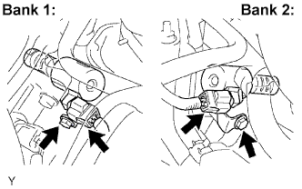

- Torque:
- 9.0 N*m{ 92 kgf*cm , 80 in.*lbf }
Connect the 2 connectors.
| 2. INSTALL INTAKE AIR SURGE TANK |
Install a new gasket onto the intake air surge tank.
Using a socket hexagon wrench 8, install the intake air surge tank with the 4 bolts.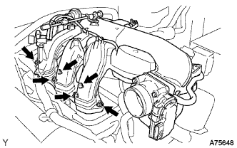
- Torque:
- 28 N*m{ 286 kgf*cm , 21 ft.*lbf }
Install the 2 nuts.
- Torque:
- 28 N*m{ 286 kgf*cm , 21 ft.*lbf }
Install the 3 wire harness clamps and hose clamp.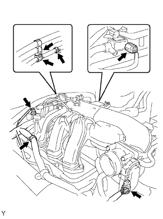
Connect the throttle body with motor connector.
Connect the 2 VSV connectors.
Connect the ventilation hose.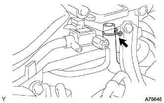
Connect the fuel vapor feed hose.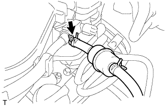
Connect the 2 water by-pass hoses.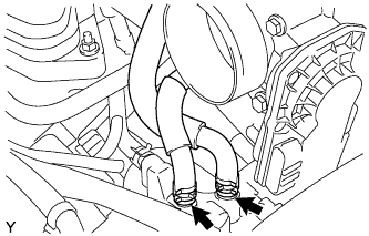
| 3. INSTALL NO. 2 SURGE TANK STAY |
Install the No. 2 surge tank stay with the 2 bolts.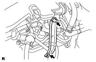
- Torque:
- 21 N*m{ 214 kgf*cm , 15 ft.*lbf }
| 4. INSTALL NO. 1 SURGE TANK STAY |
Install the No. 1 surge tank stay with the 2 bolts.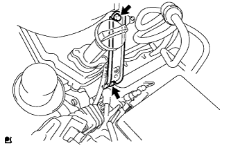
- Torque:
- 21 N*m{ 214 kgf*cm , 15 ft.*lbf }
| 5. INSTALL OIL BAFFLE PLATE |
Install the oil baffle plate with the bolt.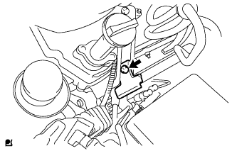
- Torque:
- 9.0 N*m{ 92 kgf*cm , 80 in.*lbf }
| 6. INSTALL THROTTLE BODY BRACKET |
Install the throttle body bracket with the 2 bolts.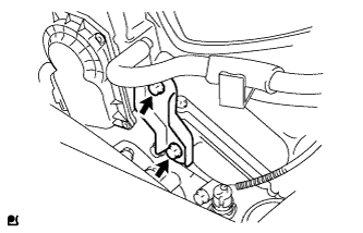
- Torque:
- 21 N*m{ 214 kgf*cm , 15 ft.*lbf }
| 7. INSTALL AIR CLEANER ASSEMBLY |
Install the air cleaner onto the throttle body.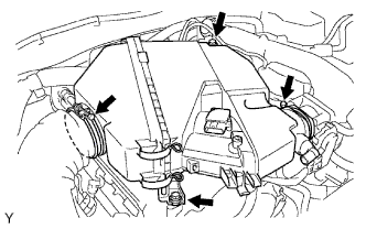
Connect the air cleaner hose to the air cleaner.
Install the air cleaner with the 2 bolts.
- Torque:
- 8.0 N*m{ 82 kgf*cm , 71 in.*lbf }
Connect the mass air flow meter connector.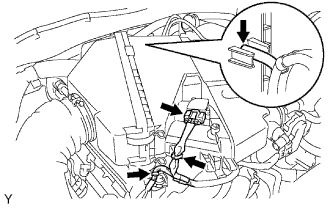
Engage the 2 wire harness clamps.
Connect the vacuum hose.
Connect the No. 2 ventilation hose.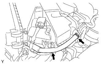
| 8. CONNECT CABLE TO NEGATIVE BATTERY TERMINAL |
- Torque:
- 3.9 N*m{ 40 kgf*cm , 35 in.*lbf }
| 9. ADD ENGINE COOLANT |
Pour coolant into the radiator until it overflows.
- Capacity:
Transmission
Capacity
Manual Transmission
9.4 liters (9.9 Us qts, 8.3 Imp. qts)
Automatic Transmission
9.8 liters (10.4 Us qts, 8.6 Imp. qts)
- NOTICE:
- Do not substitute plain water for engine coolant.
- HINT:
- Use of improper coolants may damage the engine cooling system.
- Use only TOYOTA SLLC or similar high quality ethylene glycol based non-silicate, non-amine, non-nitrite, and non-borate coolant with long-life hybrid organic acid technology (coolant with long-life hybrid organic acid technology consists of a combination of low phosphates and organic acids).
- New TOYOTA vehicles are filled with TOYOTA SLLC (color is pink, premixed ethylene glycol concentration is approximately 50 % and freezing temperature is -35°C (-31°F)). When replacing the coolant, TOYOTA SLLC is recommended.
- Use of improper coolants may damage the engine cooling system.
Check the coolant level inside the radiator by squeezing the inlet and outlet radiator hoses several times by hand. If the coolant level goes down, add coolant.
Install the radiator cap securely.
Slowly pour coolant into the radiator reservoir until it reaches the FULL line.
Warm up the engine until the cooling fan operates.
Set the air conditioning as follows while warming up the engine.
Item
Condition
Fan Speed
Any setting except OFF
Temperature
Toward WARM
Air Conditioning Switch
OFF
Maintain the engine speed at 2,000 to 2,500 rpm and warm up the engine until the cooling fan operates.
- NOTICE:
- Make sure that the radiator reservoir still has some coolant in it.
- Pay attention to the needle of the water temperature meter. Make sure that the needle does not show an abnormally high temperature.
- If there is not enough coolant, the engine may burn out or overheat.
- Make sure that the radiator reservoir still has some coolant in it.
Squeeze the inlet and outlet radiator hoses several times by hand while warming up the engine to bleed the air.
- CAUTION:
-
When pressing the radiator hoses:
- Wear protective gloves.
- Be careful as the radiator hoses are hot.
- Keep your hands away from the fan.
- Wear protective gloves.
Stop the engine and wait until the coolant cools down.
Remove the radiator cap and check the coolant level inside the radiator.
If the coolant level is below the full level, repeat the operation until the coolant level remains at the full level.
Check the coolant level inside the radiator reservoir tank again. If it is below the full level, add coolant.
| 10. CHECK FOR ENGINE COOLANT LEAK |
Fill the radiator with coolant and attach a radiator cap tester.
Pump it to 177 kPa (1.8 kgf/cm2 25.7 psi), then check for leakage.
| 11. INSTALL V-BANK COVER |
Install the V-bank cover with the 2 nuts.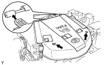
- Torque:
- 7.5 N*m{ 76 kgf*cm , 66 in.*lbf }