1.
DISCONNECT CABLE FROM NEGATIVE BATTERY TERMINAL
2.
DRAIN ENGINE COOLANT
CAUTION:
To avoid the danger of being burned, do not remove the radiator cap while the engine and radiator are still hot. Thermal expansion will cause hot engine coolant and steam to blow out from the radiator.
Remove the service hole cover from the engine under cover.
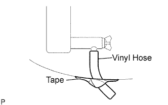
Install a vinyl hose onto the drain on the radiator side.
Fix the vinyl hose with tape.
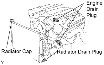
Loosen the 3 drain plugs on the engine and radiator, and drain the coolant.
Remove the radiator cap.
Drain the coolant from the reservoir tank.
Tighten the 3 drain plugs.
Torque:
13 N*m{
130 kgf*cm
, 9 ft.*lbf
}
for the engine
Remove the vinyl hose from the radiator.
3.
REMOVE V-BANK COVER
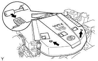
Remove the 2 nuts, then remove the V-bank cover.
4.
REMOVE AIR CLEANER ASSEMBLY
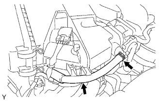
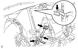
Disconnect the No. 2 ventilation hose.
Disconnect the vacuum hose.
Disconnect the mass air flow meter connector.
Disengage the 2 wire harness clamps.
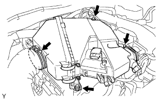
Loosen the 2 hose clamps.
Remove the 2 bolts.
Disconnect the air cleaner hose and remove the air cleaner.
5.
REMOVE THROTTLE BODY BRACKET
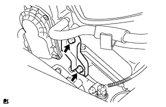
Remove the 2 bolts and the throttle body bracket.
6.
REMOVE OIL BAFFLE PLATE
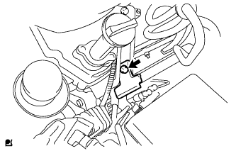
Remove the bolt and the oil baffle plate.
7.
REMOVE NO. 1 SURGE TANK STAY
Remove the 2 bolts and the throttle body bracket.
8.
REMOVE NO. 2 SURGE TANK STAY
Remove the 2 bolts and the No. 2 surge tank stay.
9.
REMOVE INTAKE AIR SURGE TANK
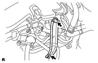
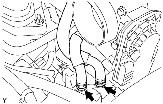
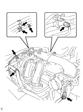
Disconnect the 2 water by-pass hoses.
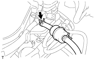
Disconnect the fuel vapor feed hose.
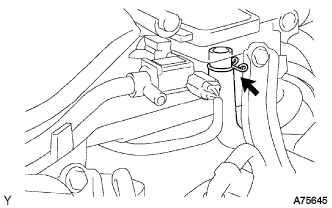
Disconnect the ventilation hose.
Disconnect the 2 VSV connectors.
Disconnect the throttle body with motor connector.
Separate the 3 wire harness clamps and the hose clamp.
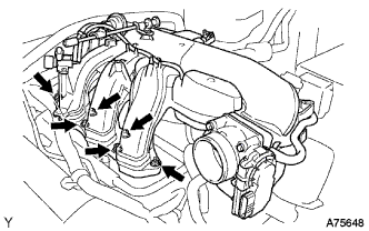
Remove the 2 nuts.
Using a socket hexagon wrench 8, remove the 4 bolts, intake air surge tank and the gasket.
10.
REMOVE CAMSHAFT TIMING OIL CONTROL VALVE ASSEMBLY
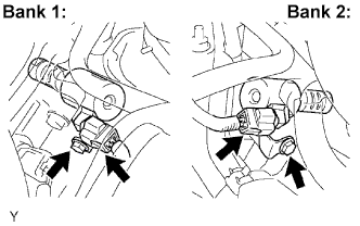
Disconnect the 2 connectors.
Remove the 2 bolts, then remove the 2 camshaft timing oil control valves.