INSTALLATION
Removal / installation · Vehicles built Jul 2007 – Jul 2009
Versions by build date: Jul 2007 – Jul 2009 Aug 2009 – Oct 2010 Nov 2010 – Jul 2013 Aug 2013 – Jul 2014 from Aug 2014
| 1.
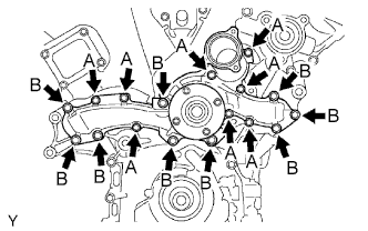
INSTALL WATER PUMP ASSEMBLY |
 |
Install a new gasket and the water pump with the 17 bolts.
-
Torque:
- For Bolt A:
- 9.0 N*m{
92 kgf*cm
, 80 in.*lbf
}
- For Bolt B:
- 23 N*m{
235 kgf*cm
, 17 ft.*lbf
}
| 2.
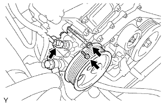
INSTALL VANE PUMP ASSEMBLY
|
|
Install the vane pump with the 2 bolts.
-
Torque:
- 43 N*m{
438 kgf*cm
, 32 ft.*lbf
}
- NOTICE:
- Do not hit the pulley with other parts when installing the vane pump.
Connect the power steering pressure switch connector.
| 3.
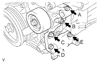
INSTALL V-RIBBED BELT TENSIONER ASSEMBLY
|
|
- NOTICE:
- The bolt in position A is not reusable.
- HINT:
- Each bolt length is as follows:
Position
|
Length
|
A
|
70 mm (2.76 in.)
|
B, C, D and E
|
33 mm (1.30 in.)
|
Use a new bolt in position A.
Finger-tighten the bolts in positions A and E and install the bracket.
Tighten the bolts in positions A and E.
-
Torque:
- 36 N*m{
267 kgf*cm
, 27 ft.*lbf
}
Tighten the bolts in positions B, C and D.
-
Torque:
- 36 N*m{
267 kgf*cm
, 27 ft.*lbf
}
| 4.
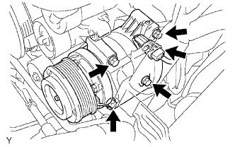
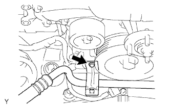
INSTALL COOLER COMPRESSOR ASSEMBLY
|
|
- Install the cooler compressor assembly with the 4 bolts.
-
Torque:
- 24.5 N*m{
250 kgf*cm
, 18 ft.*lbf
}
Connect the cooler compressor assembly connector.
- Install the suction hose sub-assembly with the bolt.
-
Torque:
- 7.8 N*m{
80 kgf*cm
, 69 in.*lbf
}
| 5.
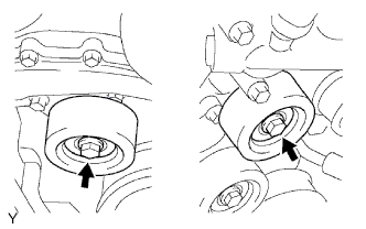
INSTALL NO. 2 IDLER PULLEY SUB-ASSEMBLY
|
|
Install the 2 No. 2 idler pulleys with the 2 bolts.
-
Torque:
- 54 N*m{
551 kgf*cm
, 40 ft.*lbf
}
| 6.
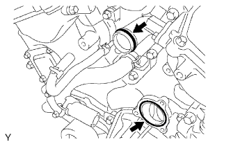
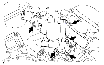
INSTALL WATER INLET |
|
Install a new O-ring onto the water outlet pipe.
Install a new gasket onto the water pump.
Apply soapy water to the O-ring.
- Install the water inlet with the 5 bolts.
-
Torque:
- 9.0 N*m{
92 kgf*cm
, 80 in.*lbf
}
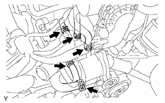
- Connect the 5 water by-pass hoses.
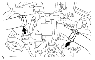
- Connect the 2 radiator hoses.
Connect the oil cooler hoses. (w/ Oil Cooler)
| 7.
INSTALL GENERATOR ASSEMBLY |
|
Refer to the procedures up to "INSTALL GENERATOR ASSEMBLY" (Click here)
| 8.
INSTALL AIR CLEANER ASSEMBLY
|
|
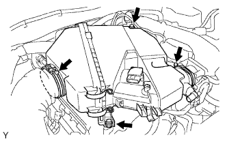
- Install the air cleaner onto the throttle body.
Connect the air cleaner hose to the air cleaner.
Install the air cleaner with the 2 bolts.
-
Torque:
- 8.0 N*m{
82 kgf*cm
, 71 in.*lbf
}
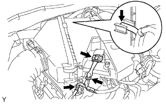
- Connect the mass air flow meter connector.
Engage the 2 wire harness clamps.
Connect the vacuum hose.
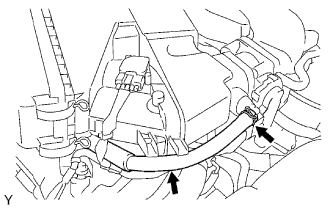
- Connect the No. 2 ventilation hose.
| 9.
INSTALL FAN |
|
Refer to the procedures up to "INSTALL FAN" (Click here).
| 10.
INSTALL V-BANK COVER
|
|
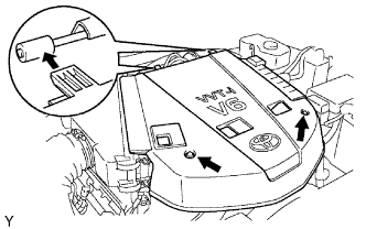
- Install the V-bank cover with the 2 nuts.
-
Torque:
- 7.5 N*m{
76 kgf*cm
, 66 in.*lbf
}