Only Passenger Door LOCK / UNLOCK Functions do not Operate
Circuit diagnosis · Vehicles built from Nov 2010
Versions by build date: Jul 2007 – Oct 2010 from Nov 2010
DESCRIPTION
The main body ECU receives lock/unlock switch signals and activates the door lock motor accordingly.WIRING DIAGRAM
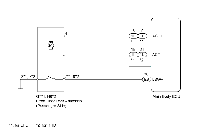

INSPECTION PROCEDURE
| 1. INSPECT FRONT DOOR LOCK ASSEMBLY (PASSENGER SIDE) |

Inspect the front door lock assembly (passenger side) (Click here).
|
|
||||

| OK | |
 |
| 2. CHECK HARNESS AND CONNECTOR (MAIN BODY ECU - FRONT DOOR LOCK ASSEMBLY (PASSENGER SIDE)) |
Disconnect the 1L and E6 main body ECU connectors.
for LHD
Disconnect the G7 front door lock assembly (passenger side) connector.
for RHD
Disconnect the H6 front door lock assembly (passenger side) connector.
Measure the resistance according to the value(s) in the table below.
- Standard Resistance:
for LHD Tester Connection
Condition
Specified Condition
1L-6 (ACT+) - G7-4
Always
Below 1 Ω
1L-18 (ACT-) - G7-1
Always
Below 1 Ω
E6-30 (LSWP) - G7-7
Always
Below 1 Ω
G7-8 - Body ground
Always
Below 1 Ω
1L-6 (ACT+) - Body ground
Always
10 kΩ or higher
1L-18 (ACT-) - Body ground
Always
10 kΩ or higher
E6-30 (LSWP) - Body ground
Always
10 kΩ or higher
for RHD Tester Connection
Condition
Specified Condition
1L-9 (ACT+) - H6-4
Always
Below 1 Ω
1L-21 (ACT-) - H6-1
Always
Below 1 Ω
E6-30 (LSWP) - H6-8
Always
Below 1 Ω
H6-7 - Body ground
Always
Below 1 Ω
1L-9 (ACT+) - Body ground
Always
10 kΩ or higher
1L-21 (ACT-) - Body ground
Always
10 kΩ or higher
E6-30 (LSWP) - Body ground
Always
10 kΩ or higher
Reconnect the front door lock assembly (passenger side) connector.
Reconnect the main body ECU connectors.
|
|
||||
| OK | ||
 |
||
| ||