Only Back Door LOCK / UNLOCK Functions do not Operate
Circuit diagnosis · Vehicles built Jul 2007 – Oct 2010
Versions by build date: Jul 2007 – Oct 2010 from Nov 2010
DESCRIPTION
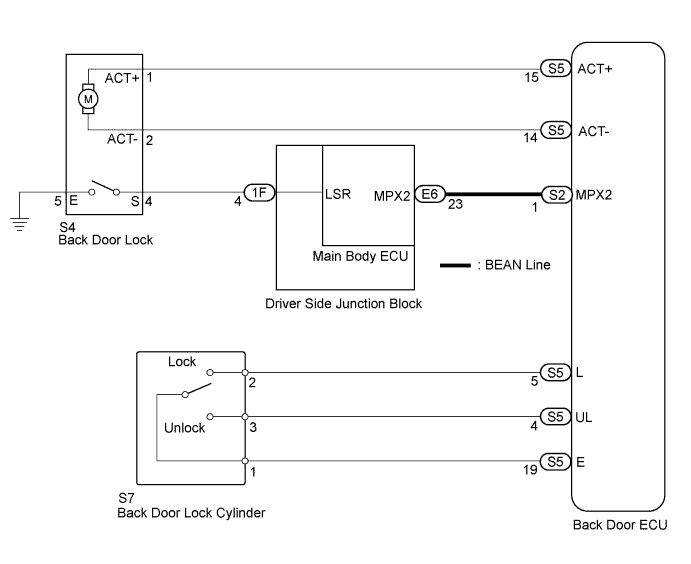
The back door ECU receives lock/unlock signals and activates the door lock motor accordingly.WIRING DIAGRAM

INSPECTION PROCEDURE
| 1. PERFORM ACTIVE TEST USING INTELLIGENT TESTER |

Connect a intelligent tester to the DLC3.
Turn the ignition switch to ON.
Turn the tester ON.
Enter the following menus: Body Electrical / Main Body / Active Test.
According to the display on tester, perform the "Active Test".
| Tester Display |
Test Part |
Control Range |
Diagnostic Note |
| Door Lock |
Operate back door lock motor |
LOCK/UNLOCK |
- |
- Result:
Result
Proceed to
Back door lock function cannot be operated
A
Back door lock function can be operated
B
|
|
||||

| A | |
 |
| 2. CHECK DTC OUTPUT (MULTIPLEX COMMUNICATION SYSTEM) |
Use a intelligent tester to check check DTC output (Click here).
- Result:
Result
Proceed to
DTC is output
A
DTC is not output
B
|
|
||||
| A | ||
 |
||
| ||
| 3. INSPECT BACK DOOR LOCK CYLINDER |
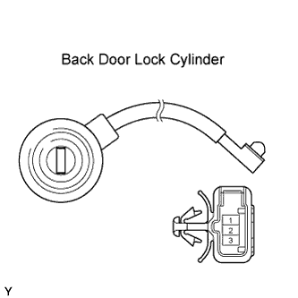 |
Remove the back door lock cylinder (Click here).
Measure the resistance according to the value(s) in the table below.
- Standard resistance:
Tester Connection (Symbols)
Key Condition
Specified Condition
1 - 2
Lock position
Below 1 Ω
1 - 2
Unlock position
10 kΩ or higher
1 - 3
Lock position
10 kΩ or higher
1 - 3
Unlock position
Below 1 Ω
Reinstall the the back door lock cylinder.
|
|
||||

| OK | |
|
| 4. CHECK HARNESS AND CONNECTOR (BACK DOOR LOCK CYLINDER - BACK DOOR ECU) |
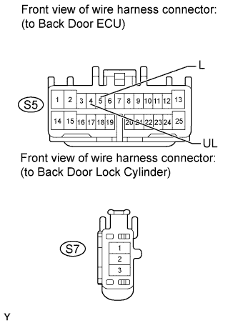 |
Disconnect the S5 back door ECU connector.
Disconnect the S7 back door lock cylinder connector.
Measure the resistance according to the value(s) in the table below.
- Standard resistance:
Tester Connection
Condition
Specified Condition
S7-2 - S5-5 (L)
Always
Below 1 Ω
S7-3 - S5-4 (UL)
Always
Below 1 Ω
S7-2 or S5-5 (L) - Body ground
Always
10 kΩ or higher
S7-3 or S5-4 (UL) - Body ground
Always
10 kΩ or higher
Reconnect the back door ECU connector.
Reconnect the back door lock cylinder connector.
|
|
||||
| OK | ||
|
||
| ||
| 5. INSPECT BACK DOOR LOCK |
Remove the back door lock (Click here).
Apply the battery voltage to the door lock motor and check the operation of the door lock motor.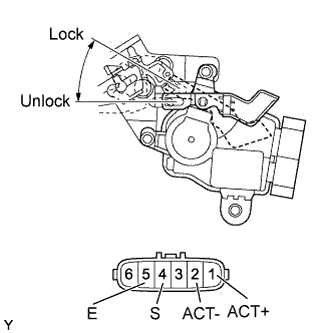
- Standard:
Measurement Condition
Specified Condition
Battery positive (+) → Terminal 1 (ACT+)
Battery negative(-) → Terminal 2 (ACT-)
Locks
Battery positive (+) → Terminal 2 (ACT-)
Battery negative(-) → Terminal 1 (ACT+)
Unlocks
Measure the resistance according to the value(s) in the table below.
- Standard resistance:
Tester Connection
Door Lock Condition
Specified Condition
4 (S) - 5 (E)
Locked
10 kΩ or higher
4 (S) - 5 (E)
Unlocked
Below 1 Ω
|
|
||||
| OK | |
|
| 6. CHECK HARNESS AND CONNECTOR (MAIN BODY ECU - BACK DOOR LOCK) |
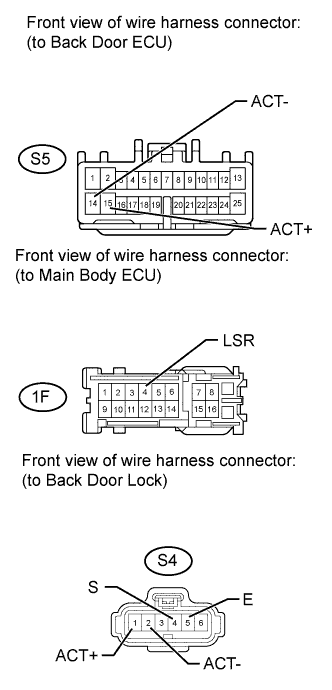 |
Disconnect the 1F main body ECU connector.
Disconnect the S4 back door lock connector.
Disconnect the S5 back door ECU connector.
Measure the resistance according to the value(s) in the table below.
- Standard resistance:
Tester Connection
Condition
Specified Condition
S5-15 (ACT+) - S4-1 (ACT+)
Always
Below 1 Ω
S5-14 (ACT-) - S4-2 (ACT-)
Always
Below 1 Ω
1F-4 (LSR) - S4-4 (S)
Always
Below 1 Ω
S4-5 (E) - Body ground
Always
Below 1 Ω
S5-15 (ACT+) or S4-1 (ACT+) - Body ground
Always
10 kΩ or higher
S5-14 (ACT-) or S4-2 (ACT-) - Body ground
Always
10 kΩ or higher
1F-4 (LSR) or S4-4 (S) - Body ground
Always
10 kΩ or higher
Reconnect the main body ECU connector.
Reconnect the back door lock connector.
Reconnect the back door ECU connector.
|
|
||||
| OK | ||
|
||
| ||