Power Windows do not Operate at All
Circuit diagnosis · Vehicles built Jul 2007 – Oct 2010
Versions by build date: Jul 2007 – Oct 2010 Nov 2010 – Jul 2011 from Aug 2011
DESCRIPTION
If all of the power windows do not operate, the power window regulator master switch may have no power or may be malfunctioning.WIRING DIAGRAM
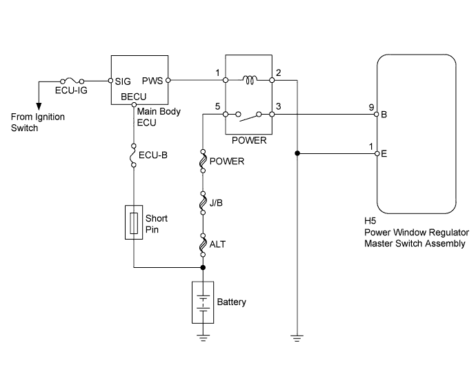

INSPECTION PROCEDURE
| 1. CHECK FUSES (ECU-IG, ECU-B) |

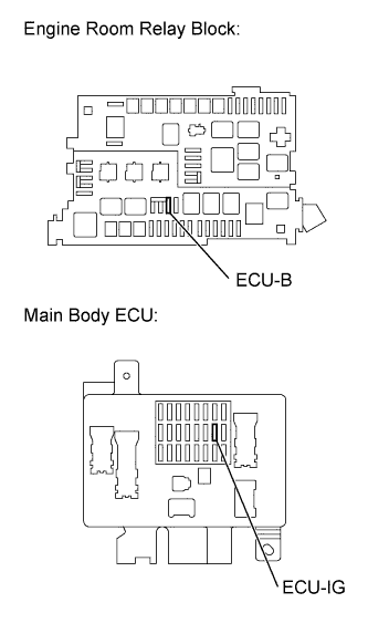 |
Remove the ECU-IG fuse from the main body ECU.
Remove the ECU-B fuse from engine room relay block.
Check the fuses resistance.
- Standard resistance:
Tester Connection
Condition
Specified Condition
ECU-IG fuse
Always
Below 1 Ω
ECU-B fuse
Always
Below 1 Ω
Reinstall the ECU-B fuse.
Reinstall the ECU-IG fuse.
|
|
||||

| OK | |
 |
| 2. INSPECT RELAY |
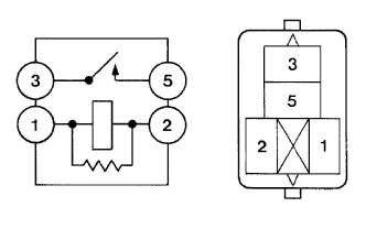 |
Remove the POWER relay from the main body ECU.
Check the POWER relay resistance.
- Standard resistance:
Tester Connection
Specified Condition
3 - 5
10 kΩ or higher
(when battery voltage absent)
3 - 5
Below 1 Ω
(when battery voltage applied to terminals 1 and 2)
Reinstall the POWER relay.
|
|
||||
| OK | |
|
| 3. CHECK HARNESS AND CONNECTOR (MASTER SWITCH - BATTERY AND BODY GROUND) |
Disconnect the H5 power window regulator master switch assembly connector.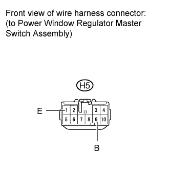
Measure the voltage according to the value(s) in the table below.
- Standard voltage:
Tester Connection
Condition
Specified Condition
H5-9 (B) - Body ground
Ignition switch ON
11 to 14 V
Measure the resistance according to the value(s) in the table below.
- Standard resistance:
Tester Connection
Condition
Specified Condition
H5-1 (E) - Body ground
Always
Below 1 Ω
Reconnect the master switch connector.
|
|
||||
| OK | |
|
| 4. INSPECT POWER WINDOW REGULATOR MASTER SWITCH ASSEMBLY |
Remove the power window regulator master switch assembly.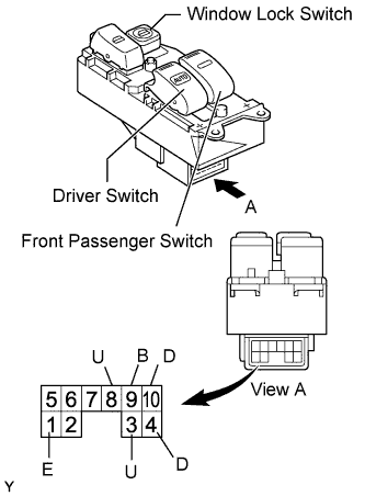
Measure the resistance according to the value(s) in the table below.
- Standard resistance:
Tester Connection
Power Window Switch Condition
Tester Connection
Specified Condition
Always
(ON / OFF)
UP
1 (E) - 4 (D)
3 (U) - 9 (B)
Below 1 Ω
Always
(ON / OFF)
OFF
1 (E) - 3 (U)
1 (E) - 4 (D)
Below 1 Ω
Always
(ON / OFF)
DOWN
1 (E) - 3 (U)
4 (D) - 9 (B)
Below 1 Ω
Always
(ON / OFF)
AUTO DOWN
1 (E) - 3 (U)
4 (D) - 9 (B)
Below 1 Ω
OFF
UP
1 (E) - 10 (D)
8 (U) - 9 (B)
Below 1 Ω
OFF
OFF
1 (E) - 8 (U)
1 (E) - 10 (D)
Below 1 Ω
OFF
DOWN
1 (E) - 8 (U)
9 (B) - 10 (D)
Below 1 Ω
ON
UP
1 (E) - 10 (D)
10 kΩ or higher
8 (U) - 9 (B)
Below 1 Ω
ON
OFF
8 (U) - 10 (D)
Below 1 Ω
ON
DOWN
1 (E) - 8 (U)
10 kΩ or higher
9 (B) - 10 (D)
Below 1 Ω
Reinstall the master switch.
|
|
||||
| OK | ||
 |
||
| ||