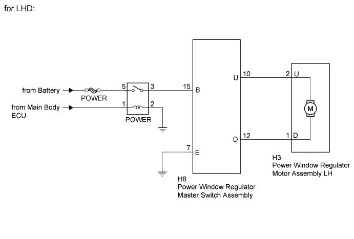
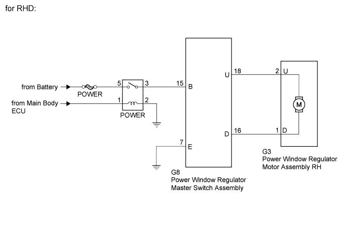
If the manual UP / DOWN and AUTO DOWN functions do not operate, a malfunction may be present in the power window regulator master switch, power window regulator motor or wire harness.
WIRING DIAGRAM
INSPECTION PROCEDURE
NOTICE:
Inspect the fuses for circuits related to this system before performing the following inspection procedure.
1. CHECK HARNESS AND CONNECTOR (POWER WINDOW REGULATOR MASTER SWITCH ASSEMBLY - POWER RELAY AND GROUND)
Disconnect the H8 or G8 power window regulator master switch assembly connector.
Turn the ignition switch to ON.
Measure the voltage and resistance according to the value(s) in the table below.
Standard Voltage:
for LHD
Tester Connection
Switch Condition
Specified Condition
H8-15 (B) - Body ground
Ignition switch ON
11 to 14 V
for RHD
Tester Connection
Switch Condition
Specified Condition
G8-15 (B) - Body ground
Ignition switch ON
11 to 14 V
Standard Resistance:
for LHD
Tester Connection
Condition
Specified Condition
H8-7 (E) - Body ground
Always
Below 1 Ω
for RHD
Tester Connection
Condition
Specified Condition
G8-7 (E) - Body ground
Always
Below 1 Ω
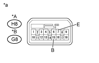
Text in Illustration
*A
for LHD
*B
for RHD
*a
Front view of wire harness connector (to Power Window Regulator Master Switch Assembly)
Reconnect the power window regulator master switch assembly connector.
NG
REPAIR OR REPLACE HARNESS OR CONNECTOR
OK
2. INSPECT POWER WINDOW REGULATOR MASTER SWITCH ASSEMBLY
Inspect the power window regulator master switch assembly (Click here).
NG
REPLACE POWER WINDOW REGULATOR MASTER SWITCH ASSEMBLY (Click here)
OK
3. CHECK HARNESS AND CONNECTOR (POWER WINDOW REGULATOR MASTER SWITCH - POWER WINDOW REGULATOR MOTOR ASSEMBLY)
Disconnect the H8 or G8 power window regulator master switch assembly connector.
Disconnect the H3 or G3 power window regulator motor assembly connector.
Measure the resistance according to the value(s) in the table below.
Standard Resistance:
for LHD
Tester Connection
Condition
Specified Condition
H8-12 (D) - H3-1 (D)
Always
Below 1 Ω
H8-10 (U) - H3-2 (U)
Always
Below 1 Ω
H8-12 (D) or H3-1 (D) - Body ground
Always
10 kΩ or higher
H8-10 (U) or H3-2 (U) - Body ground
Always
10 kΩ or higher
for RHD
Tester Connection
Condition
Specified Condition
G8-16 (D) - G3-1 (D)
Always
Below 1 Ω
G8-18 (U) - G3-2 (U)
Always
Below 1 Ω
G8-16 (D) or G3-1 (D) - Body ground
Always
10 kΩ or higher
G8-18 (U) or G3-2 (U) - Body ground
Always
10 kΩ or higher
Reconnect the motor connector.
Reconnect the master switch connector.
Result
Result
Proceed to
NG
A
OK (for LHD)
B
OK (for RHD)
C
B
REPLACE POWER WINDOW REGULATOR MOTOR ASSEMBLY LH (Click here)
C
REPLACE POWER WINDOW REGULATOR MOTOR ASSEMBLY RH (Click here)