Removal / installation · Vehicles built Jul 2007 – Oct 2010
Versions by build date: Jul 2007 – Oct 2010from Nov 2010
1.
INSTALL TRANSFER ASSEMBLY
Install the transfer onto the transmission.
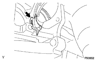
Install the 2 clamps and 8 bolts.
Torque:
24 N*m{
244 kgf*cm
, 17 ft.*lbf
}
2.
INSPECT TORQUE CONVERTER CLUTCH ASSEMBLY
Inspect the one-way clutch.
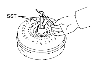
Install SST in the inner race of the one-way clutch.
SST
09350-32014
(09351-32020)
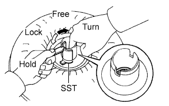
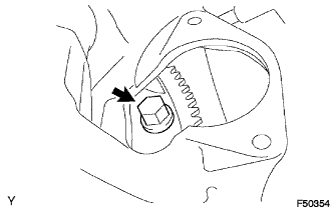
Press on the serrations of the starter with a finger and rotate it. Check if it rotates smoothly when turned clockwise and locks when turned counterclockwise. If the results are not as specified, clean the converter and recheck the one-way clutch. If the results still are not as specified, replace the converter
Determine the condition of the torque converter clutch.
Check that the following conditions are met:
During the stall test or when the shift lever is in N, metallic sounds are not emitted from the torque converter clutch.
The one-way clutch turns in one direction and locks in the other direction.
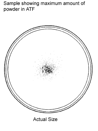
The amount of powder in the ATF is not greater than the sample shown in the illustration.
If the results are not as specified, replace the torque converter clutch assembly.
HINT:
The sample illustration shows approximately 0.25 liters (0.26 US qts, 0.22 Imp. qts) of the ATF taken from a removed torque converter clutch.
Replace the ATF in the torque converter clutch.
If the ATF is discolored and/or has a foul odor, stir the ATF in the torque converter clutch thoroughly and drain the ATF with the torque converter facing up.
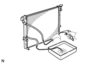
Clean and check the oil cooler and oil pipe line.
If the torque converter clutch is inspected or the ATF is replaced, clean the oil cooler and oil pipe line.
HINT:
Apply compressed air of 196 kPa (2 kgf/cm2, 28 psi) into the inlet hose.
If a large amount of powder is found in the ATF, add new ATF using a bucket pump and clean the oil cooler and oil pipe line again.
If the ATF is cloudy, inspect the oil cooler (radiator).
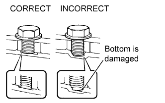
Prevent deformation of the torque converter clutch and damage to the oil pump gear.
When any marks due to interference are found on the end of the bolt for the torque converter clutch and on the bottom of the bolt hole, replace the bolt and torque converter clutch.
All of the bolts should be the same length.
Make sure no spring washers are missing.
3.
INSTALL TORQUE CONVERTER CLUTCH ASSEMBLY
Install the torque converter clutch onto the automatic transmission.
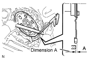
Using calipers and a straight edge, measure dimension A, between the engine and the end surface of the drive plate, shown in the illustration.
Standard:
A = 21.2 mm (0.835 in.)
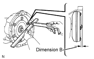
Using calipers and a straight edge, measure dimension B shown in the illustration. Check that B is greater than A.
Standard:
B = A+1.0 mm (0.0394 in.) or more
4.
INSTALL AUTOMATIC TRANSMISSION WITH TRANSFER
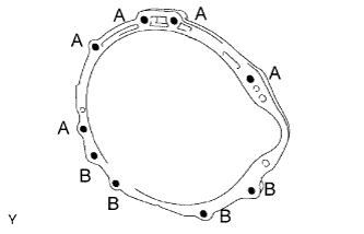
Install the automatic transmission onto the engine with the 9 bolts.
Torque:
71 N*m{
720 kgf*cm
, 53 ft.*lbf
}
for bolt A
37 N*m{
380 kgf*cm
, 27 ft.*lbf
}
for bolt B
Install the 6 torque converter clutch mounting bolts.
Torque:
48 N*m{
489 kgf*cm
, 35 ft.*lbf
}
HINT:
First install the black bolt and then the other 5 bolts.
5.
INSTALL FLYWHEEL HOUSING SIDE COVER
Install the flywheel housing side cover onto the cylinder block.
6.
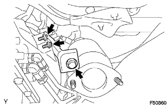
INSTALL STARTER ASSEMBLY
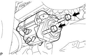
Install the starter assembly with 2 bolts.
Torque:
37 N*m{
377 kgf*cm
, 27 ft.*lbf
}
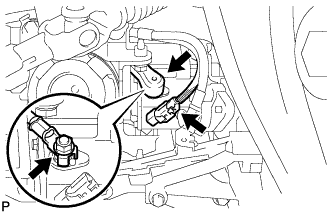
Connect the wire harness to the terminal 30, then install the nut.
Torque:
5.9 N*m{
60 kgf*cm
, 52 in.*lbf
}
Connect the terminal 50 connector to the starter assembly.
7.
CONNECT WIRE HARNESS
8.
CONNECT CONNECTOR
Connect the 3 indicator switch connectors.
Connect the 2 speed sensor connectors.
Connect the transmission wire connector.
Connect the park/neutral position switch connector.
9.
INSTALL REAR NO.1 ENGINE MOUNTING INSULATOR
Install the engine mounting insulator rear onto the automatic transmission with the 4 bolts.
Torque:
65 N*m{
663 kgf*cm
, 48 ft.*lbf
}
10.
INSTALL NO. 3 FRAME CROSSMEMBER SUB-ASSEMBLY
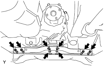
Install the No. 3 frame crossmember sub-assembly with the 4 bolts and 4 nuts.
Torque:
72 N*m{
734 kgf*cm
, 53 ft.*lbf
}
Install the No. 3 frame crossmember sub-assembly with the 4 bolts.
Torque:
19 N*m{
189 kgf*cm
, 14 ft.*lbf
}
11.
INSTALL FRONT SUSPENSION MEMBER BRACKET LH
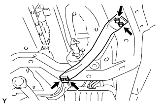
Install the front suspension member bracket LH with the 4 bolts.
Torque:
33 N*m{
336 kgf*cm
, 24 ft.*lbf
}
12.
INSTALL FRONT SUSPENSION MEMBER BRACKET RH
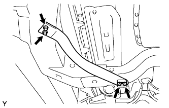
Install the front suspension member bracket RH with the 4 bolts.
Torque:
33 N*m{
336 kgf*cm
, 24 ft.*lbf
}
13.
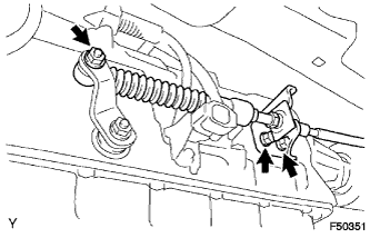
INSTALL TRANSMISSION CONTROL CABLE ASSEMBLY
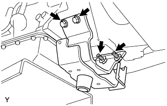
Install the transmission control cable bracket with the 2 bolts.
Torque:
14 N*m{
143 kgf*cm
, 10 ft.*lbf
}
Connect the transmission control cable with the nut.
Torque:
14 N*m{
143 kgf*cm
, 10 ft.*lbf
}
14.
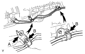
INSTALL OIL COOLER TUBE
Provisionally install the No. 1 oil cooler outlet tube.
Provisionally install the No. 1 oil cooler inlet tube.
Install the 2 clamps and 2 bolts.
Torque:
14 N*m{
138 kgf*cm
, 10 ft.*lbf
}
for bolt A
5.5 N*m{
56 kgf*cm
, 49 in.*lbf
}
for bolt B
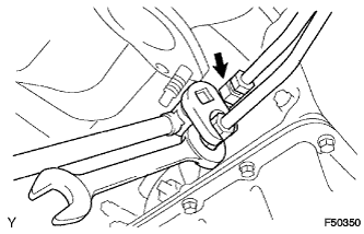
Using SST, tighten the No. 1 oil cooler outlet tube.
SST
09023-12701
Torque:
34 N*m{
350 kgf*cm
, 25 ft.*lbf
}
for use without SST
30 N*m{
306 kgf*cm
, 22 ft.*lbf
}
for use with SST
HINT:
Use a torque wrench with a fulcrum length of 300 mm (11.81 in.).
This torque value is effective when SST is parallel to the torque wrench.
Using SST, tighten the No. 1 oil cooler inlet tube.
SST
09023-12701
Torque:
34 N*m{
350 kgf*cm
, 25 ft.*lbf
}
for use without SST
30 N*m{
306 kgf*cm
, 22 ft.*lbf
}
for use with SST
HINT:
Use a torque wrench with a fulcrum length of 300 mm (11.81 in.).
This torque value is effective when SST is parallel to the torque wrench.
15.
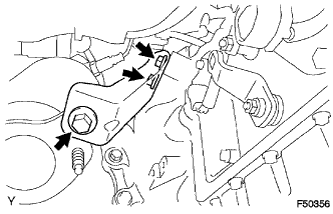
INSTALL NO. 2 MANIFOLD STAY
Install No. 2 manifold stay with the 3 bolts.
Torque:
40 N*m{
408 kgf*cm
, 30 ft.*lbf
}
16.
INSTALL MANIFOLD STAY
Install the manifold stay with the 3 bolts.
Torque:
40 N*m{
408 kgf*cm
, 30 ft.*lbf
}
17.
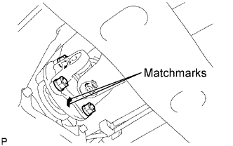
INSTALL PROPELLER SHAFT ASSEMBLY
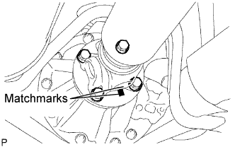
Align the matchmarks on the propeller shaft flange and differential flange.
Install the propeller shaft assembly with the 4 bolts, 4 nuts and 4 washers.
Torque:
88 N*m{
899 kgf*cm
, 65 ft.*lbf
}
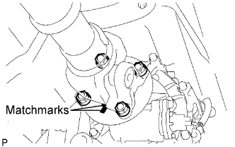
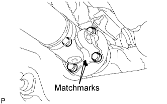
Align the matchmarks on the propeller shaft flange and transfer flange.
Install the propeller shaft assembly with the 4 nuts and 4 washers.
Torque:
88 N*m{
899 kgf*cm
, 65 ft.*lbf
}
18.
INSTALL FRONT PROPELLER SHAFT ASSEMBLY
Align the matchmarks on the yoke and differential flange.
Install the propeller shaft assembly with the 4 bolts, 4 nuts and 4 washers.
Torque:
88 N*m{
899 kgf*cm
, 65 ft.*lbf
}
Align the matchmarks on the yoke and transfer flange.
Install the propeller shaft assembly with the 4 nuts and 4 washers.
Torque:
88 N*m{
899 kgf*cm
, 65 ft.*lbf
}
19.
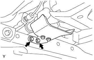
INSTALL PROPELLER SHAFT HEAT INSULATOR
Install the propeller shaft heat insulator with the 2 bolts.
Torque:
16 N*m{
160 kgf*cm
, 12 ft.*lbf
}
20.
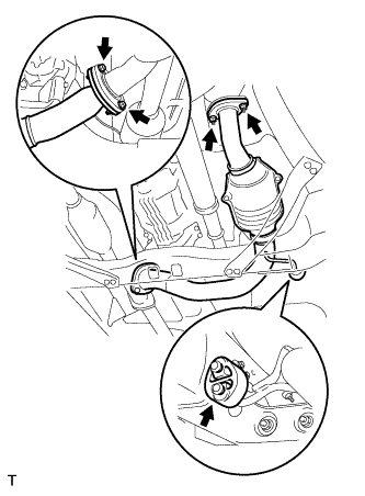
INSTALL FRONT EXHAUST PIPE ASSEMBLY
Install a new gasket onto the exhaust manifold RH.
Install the exhaust front pipe with new 2 nuts.
Torque:
54 N*m{
554 kgf*cm
, 40 ft.*lbf
}
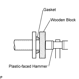
Install a new gasket onto the front exhaust pipe.
Using a wooden block and plastic-faced hammer, tap in a new gasket until it is flush with the front exhaust pipe end.
NOTICE:
Make sure that the gasket is in the correct direction when installing.
Do not reuse the removed gasket.
Do not push in the gasket with the exhaust pipe when connecting it.
21.
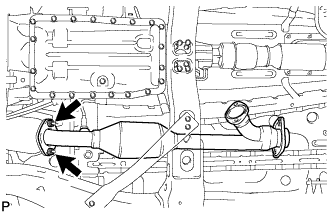
INSTALL NO. 2 EXHAUST FRONT PIPE ASSEMBLY
Install a new gasket onto the exhaust manifold LH.
Install a new gasket onto the No. 2 front exhaust pipe.
Install the No. 2 front exhaust pipe with 2 new nuts and 2 bolts and exhaust pipe support.
Torque:
Nut:
54 N*m{
554 kgf*cm
, 40 ft.*lbf
}
Bolt:
48 N*m{
489 kgf*cm
, 35 ft.*lbf
}
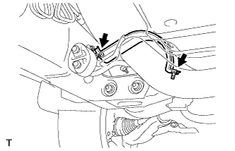
Install the exhaust pipe stopper bracket with the 2 bolts (for 4WD).
Torque:
19 N*m{
193 kgf*cm
, 14 ft.*lbf
}
22.
CONNECT OXYGEN SENSOR
23.
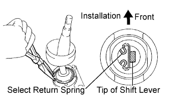
INSTALL TRANSFER HIGH AND LOW SHIFT LEVER ASSEMBLY
Install the transfer shift lever onto the shift lever retainer.
Using needle-nose pliers, install the snap ring.
24.
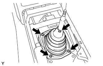
INSTALL SHIFT LEVER BOOT ASSEMBLY
Install the shift lever boot with the 4 screws.
25.
INSTALL SHIFT LEVER KNOB SUB-ASSEMBLY (for Transfer)
26.
INSTALL SHIFT LEVER ASSEMBLY (for Automatic Transmission)
Check that the shift lever moves smoothly and appropriately from the P to the R position, only when the ignition switch is turned to ON and the brake pedal is depressed.
When starting the engine, make sure that the vehicle moves forward when shifting the lever from the N to the D position and moves rearward when shifting the lever to the R position.
31.
ADJUST SHIFT LEVER POSITION
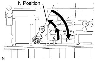
Push the control shaft fully rearward.
Turn the control shaft lever 2 notches counterclockwise to the N position.