REASSEMBLY
Removal / installation · Vehicles built Jul 2007 – Jul 2009
Versions by build date: Jul 2007 – Jul 2009 from Aug 2009
| 1. INSTALL FRONT DRIVE SHAFT DUST COVER |

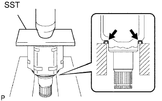  |
Using SST and a press, install a new dust cover into the inboard joint until it is flush with the end.
- SST
- 09527-10011
- NOTICE:
- Install the dust cover in the correct orientation.
- Do not deform the dust cover.
- Install the dust cover in the correct orientation.
| 2. INSTALL FRONT DRIVE SHAFT HOLE SNAP RING |
Install a new snap ring.
| 3. INSTALL OUTBOARD JOINT BOOT |
Wrap the spline of the outboard joint shaft with protective tape.
Install new parts onto the outboard joint shaft in the following order.
1.
Front axle outboard joint boot No. 2 clamp
2.
Front axle outboard joint boot
3.
Front axle outboard joint boot clamp
Pack the joint portion of the outboard joint shaft and outboard joint boot with grease.
- Grease capacity:
- 260 to 270 g (9.2 to 9.5 oz.)
Install the outboard joint boot onto the outboard joint shaft groove.
- NOTICE:
- Keep the groove free of grease.
| 4. INSTALL FRONT AXLE OUTBOARD JOINT BOOT NO. 2 CLAMP |
Fix the outboard joint shaft in a vise between aluminum plates.
- NOTICE:
- Do not overtighten the vise.
Place SST onto the boot clamp, press it against the boot and slightly tighten SST.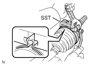
- SST
- 09521-24010
Fix SST and tighten it so that the clearance comes to within the specified range.
- Clearance:
- 0.8 mm (0.031 in.) or less
Remove SST.
Using SST, measure the clearance of the boot clamp as shown in the illustration.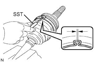
- SST
- 09240-00020
- Clearance:
- 0.8 mm (0.031 in.) or less
- NOTICE:
- If the clearance is outside the specified range, retighten it.
| 5. INSTALL FRONT AXLE OUTBOARD JOINT BOOT CLAMP |
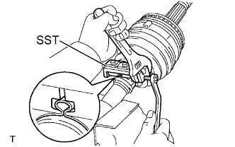 |
Place SST onto the boot clamp, press it against the boot and slightly tighten SST.
- SST
- 09521-24010
Fix SST and tighten it so that the clearance comes to within the specified range.
- Clearance:
- 0.8 mm (0.031 in.) or less
Remove SST.
Using SST, measure the clearance of the boot clamp as shown in the illustration.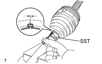
- SST
- 09240-00020
- Clearance:
- 0.8 mm (0.031 in.) or less
- NOTICE:
- If the clearance is outside the specified range, retighten it.
| 6. INSTALL FRONT DRIVE INBOARD JOINT ASSEMBLY |
Install new parts onto the outboard joint shaft in the following order.
1.
Front axle inboard joint boot clamp
2.
Front axle inboard joint boot
3.
Front axle inboard joint boot No. 2 clamp
Fix the outboard joint shaft in a vise between aluminum plates.
- NOTICE:
- Do not overtighten the vise.
Remove the protective tape.
Align the matchmarks and install the tripod joint onto the outboard joint shaft.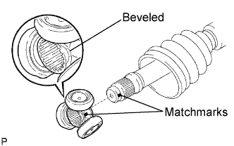
- NOTICE:
- Place the beveled side of the tripod toward the inboard joint.
Using a brass bar and hammer, install the tripod joint.
- NOTICE:
- Do not hit the roller portion.
- Keep the tripod joint free of foreign matter.
- Do not hit the roller portion.
Using a snap ring expander, install a new snap ring.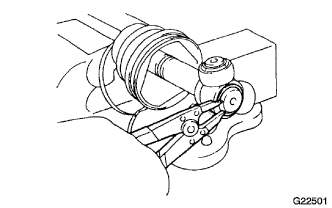
Pack the inboard joint with grease.
- Grease capacity:
- 231 to 241 g (8.1 to 8.5 oz.)
Align the matchmarks and install the inboard joint onto the outboard joint shaft.
| 7. INSTALL INBOARD JOINT BOOT |
Install the inboard joint boot into the grooves of the inboard joint and outboard joint shaft.
- NOTICE:
- Keep the grooves free of grease.
| 8. INSTALL FRONT AXLE INBOARD JOINT BOOT NO. 2 CLAMP |
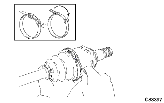 |
Install the boot clamp onto the inboard joint boot and caulk the boot clamp with a screwdriver.
- NOTICE:
- Do not damage the boot.
| 9. INSTALL FRONT AXLE INBOARD JOINT BOOT CLAMP |
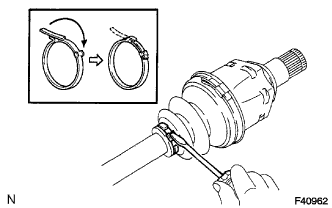 |
Install the boot clamp onto the inboard joint boot and caulk the boot clamp with a screwdriver.
- NOTICE:
- Do not damage the boot.
| 10. INSPECT FRONT DRIVE SHAFT |
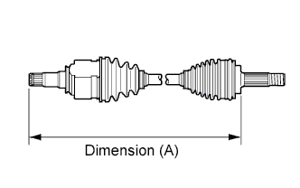 |
Check whether the drive shaft dimensions are within the following specifications.
- Dimension (A):
- 577.5 mm (22.74 in.)
Check for noticeable looseness when turning the joint up and down, left and right, and in the thrust direction.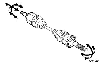
Check for cracks, damage and grease leakage on the boot joint.
- NOTICE:
- Keep the drive shaft level while moving it.