INSTALLATION
Removal / installation · Vehicles built from Aug 2012
Versions by build date: Jul 2007 – Oct 2010 Nov 2010 – Jul 2012 from Aug 2012
| 1. INSTALL BRAKE PEDAL PAD |

Install the brake pedal pad onto the brake pedal.
| 2. INSTALL STOP LIGHT SWITCH MOUNTING ADJUSTER |
Install a new stop light switch mounting adjuster onto the pedal support.
| 3. INSTALL BRAKE PEDAL RETURN SPRING |
Apply lithium soap base glycol grease to the inner surface of the hole in the brake pedal support and brake pedal.
Install the return spring onto the brake pedal support and brake pedal.
| 4. INSTALL BRAKE PEDAL SUPPORT ASSEMBLY |
Install the bolt and the brake pedal support.
- Torque:
- 20 N*m{ 204 kgf*cm , 15 ft.*lbf }
| 5. INSTALL HYDRAULIC BRAKE BOOSTER (for LHD) |
Install a new gasket onto the hydraulic brake booster.
Install the hydraulic brake booster with the 4 nuts.
- Torque:
- 14 N*m{ 145 kgf*cm , 10 ft.*lbf }
Temporarily install each brake tube to the correct positions of the brake actuator as shown in the illustration.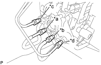

Text in Illustration *a
To front wheel cylinder RH
*b
To front wheel cylinder LH
*c
To rear wheel cylinder RH
*d
To rear wheel cylinder LH
Using a union nut wrench 10 mm, connect the 4 brake tubes onto the hydraulic brake booster.
- Torque:
- 15 N*m{ 155 kgf*cm , 11 ft.*lbf }
- NOTICE:
- Use the formula to calculate special torque values for situations where a union nut wrench is combined with a torque wrench (Click here).
Connect the 3 connectors.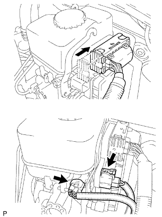
| 6. INSTALL HYDRAULIC BRAKE BOOSTER (for RHD) |
Install a new gasket onto the hydraulic brake booster.
Install the hydraulic brake booster with the 4 nuts.
- Torque:
- 14 N*m{ 145 kgf*cm , 10 ft.*lbf }
Temporarily install each brake tube to the correct positions of the brake actuator as shown in the illustration.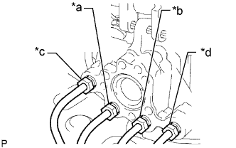
Text in Illustration *a
To front wheel cylinder RH
*b
To front wheel cylinder LH
*c
To rear wheel cylinder RH
*d
To rear wheel cylinder LH
Install the brake tube clamp to the brake tube.
Install the brake tube clamp with the bolt.
- Torque:
- 8.5 N*m{ 87 kgf*cm , 75 in.*lbf }
Using a union nut wrench 10 mm, connect the 4 brake tubes onto the hydraulic brake booster.
- Torque:
- 15 N*m{ 155 kgf*cm , 11 ft.*lbf }
- NOTICE:
- Use the formula to calculate special torque values for situations where a union nut wrench is combined with a torque wrench (Click here).
Connect the 3 connectors.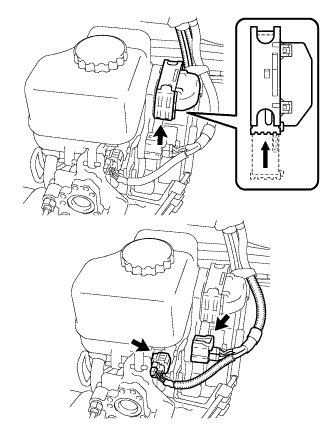
| 7. INSTALL MASTER CYLINDER PUSH ROD CLEVIS |
Apply lithium soap base glycol grease to the inner surface of the hole in the brake pedal lever.
Install the push rod clevis onto the brake pedal lever with the push rod pin and clip.
| 8. INSTALL STOP LIGHT SWITCH |
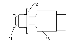 |
Insert the stop light switch into the adjuster until it just touches the brake pedal.
Text in Illustration *1
Brake pedal
*2
Stop light switch mounting adjuster
*3
Stop light switch
- NOTICE:
- Do not depress the brake pedal.
Make a quarter turn clockwise to install the stop light switch.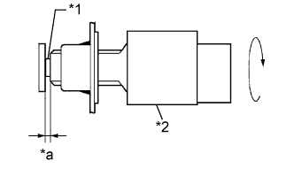
Text in Illustration *1
Shaft
*2
Stop light switch
*a
Stop light switch clearance
- NOTICE:
- Do not depress the brake pedal.
- HINT:
- The turning torque for installing the stop light switch:
- Torque:
- 1.5 N*m{ 15 kgf*cm , 13 in.*lbf } or less
Check the stop light switch clearance.
- Stop light switch clearance:
- 0.5 to 2.6 mm (0.020 to 0.102 in.)
Connect the connector to the stop light switch.
| 9. BLEED BRAKE SYSTEM |
- CAUTION:
- If air is bled without using the intelligent tester, damage or accidents may result. Therefore, always use the intelligent tester when bleeding air.
Turn the ignition switch to ON.
Remove the brake master cylinder reservoir filler cap assembly.
Add brake fluid until the fluid level is between the MIN and MAX lines of the reservoir.
Repeatedly depress the brake pedal and bleed air from the bleeder plug of the front disc brake cylinder RH.
Repeat the step above until the air is completely bled, and then tighten the bleeder plug while depressing the brake pedal.
- Torque:
- 11 N*m{ 110 kgf*cm , 8 ft.*lbf }
Bleed the air from the bleeder plug of the front disc brake cylinder LH using the same procedure as for the RH side.
With the brake pedal depressed, loosen the bleeder plug of the rear disc brake cylinder RH, continue to hold the brake pedal and allow brake fluid to be drained from the bleeder plug while the pump motor operates.
- HINT:
- Air is bled as the pump motor operates while the brake pedal is being depressed.
- Be sure to release the brake pedal to stop the motor after approximately 100 seconds of continuous operation.
- As brake fluid is continuously drained while the pump operates, it is not necessary to repeatedly depress the brake pedal.
- Air is bled as the pump motor operates while the brake pedal is being depressed.
When there is no more air in the brake fluid, tighten the bleeder plug, and then release the brake pedal.
- Torque:
- 11 N*m{ 110 kgf*cm , 8 ft.*lbf }
Bleed the air from the bleeder plug of the rear disc brake cylinder LH using the same procedure as for the RH side.
Turn the ignition switch off and connect the intelligent tester to the DLC3.
Turn the ignition switch to ON.
Turn the intelligent tester on.
Enter the following menus: Chassis / ABS/VSC/TRC / Utility / Air Bleeding.
- NOTICE:
- To protect the solenoid from overheating, the solenoid operation stops automatically in 4 seconds, and then the solenoid will not respond to commands for an additional 20 seconds.
Repeatedly depress the brake pedal several times, and then, with the brake pedal depressed, turn FR on and bleed air.
- HINT:
- Air returns to the brake master cylinder reservoir together with the brake fluid and is bled from the brake system.
- NOTICE:
- As it is not possible to visually confirm that air is being bled, repeat this step 10 times.
- Do not loosen the bleeder plug.
- As it is not possible to visually confirm that air is being bled, repeat this step 10 times.
Turn FL on and bleed air using the same procedures as for FR.
Turn RR on, loosen the bleeder plug of the rear disc brake cylinder RH and drain brake fluid.
- HINT:
- Do not depress the brake pedal.
- As brake fluid is automatically drained while the pump and solenoid operate, it is not necessary to operate the brake pedal.
- Do not depress the brake pedal.
Repeat the step above until the air is completely bled, and then tighten the bleeder plug.
- Torque:
- 11 N*m{ 110 kgf*cm , 8 ft.*lbf }
Turn FL Line on and bleed the air from the bleeder plug of the front disc brake cylinder LH using the same procedure as for the RH side.
Turn RR Line on and loosen the bleeder plug of the rear disc brake cylinder RH.
- HINT:
- Be sure to bleed air with the brake pedal depressed.
Repeat the step above until the air is completely bled, and then tighten the bleeder plug.
- Torque:
- 11 N*m{ 110 kgf*cm , 8 ft.*lbf }
Turn RL Line on and bleed air from the bleeder plug of the rear disc brake cylinder LH using the same procedure as for the RH side.
Turn the intelligent tester off and turn the ignition switch off.
Inspect for brake fluid leaks.
Check and adjust the brake fluid level (Click here).
Clear the DTCs (Click here).
| 10. INSPECT AND ADJUST BRAKE PEDAL |
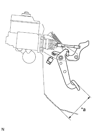 |
Inspect the brake pedal height.
Text in Illustration *a
Pedal height
If the pedal height is incorrect, adjust the rod operating adapter length.Pedal height from dash panel: for LHD
for RHD
168.7 to 178.7 mm (6.642 to 7.035 in.)
158.8 to 168.8 mm (6.252 to 6.645 in.)
Adjust the brake pedal height.
Disconnect the connector from the stop light switch.
Turn the stop light switch counterclockwise, and remove the stop light switch.
Remove the hydraulic brake booster (Click here).
Loosen the clevis lock nut.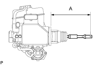
Adjust the rod operating adapter length by turning the pedal push rod clevis.
- Rod operating adapter length A:
- 201.7 to 202.7 mm (7.941 to 7.980 in.)
Tighten the clevis lock nut.
- Torque:
- 26 N*m{ 260 kgf*cm , 19 ft.*lbf }
Install the hydraulic brake booster (Click here).
Insert the stop light switch into the adjuster until it just touches the brake pedal.
Text in Illustration *1
Brake pedal
*2
Stop light switch mounting adjuster
*3
Stop light switch
- NOTICE:
- Do not depress the brake pedal.
Make a quarter turn clockwise to install the stop light switch.
Text in Illustration *1
Shaft
*2
Stop light switch
*a
Stop light switch clearance
- NOTICE:
- Do not depress the brake pedal.
- HINT:
- The turning torque for installing the stop light switch:
- Torque:
- 1.5 N*m{ 15 kgf*cm , 13 in.*lbf } or less
Check the stop light switch clearance.
- Stop light switch clearance:
- 0.5 to 2.6 mm (0.020 to 0.102 in.)
Connect the connector to the stop light switch.
Inspect the brake pedal free play.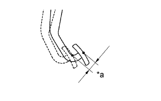
Text in Illustration *a
Pedal free play
Stop the engine and depress the brake pedal several times until there is no vacuum left in the booster.
Push in the pedal until the beginning of the resistance is felt. Measure the distance as shown.
- Pedal free play:
- 1.0 to 6.0 mm (0.0394 to 0.236 in.)
Inspect the brake pedal reserve distance.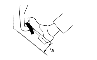
Text in Illustration *a
Pedal reserve distance
Release the parking brake pedal.
With the engine running, depress the pedal and measure the pedal reserve distance as shown.
If incorrect, troubleshoot the brake system.Pedal reserve distance from dash panel at 490 N (50 kgf, 110.2 lbf) for LHD
for RHD
More than 56 mm (2.20 in.)
More than 108 mm (4.25 in.)
| 11. INSTALL LOWER INSTRUMENT PANEL FINISH PANEL (for LHD) |
Engage the 5 clips and claw and install the lower instrument panel finish panel.
Install the 2 <E> bolts.
| 12. INSTALL LOWER INSTRUMENT PANEL FINISH PANEL (for RHD) |
Connect the connectors.
Engage the 8 clips and 4 guides and install the lower instrument panel finish panel.
Install the 2 <E> bolts.
| 13. INSTALL INSTRUMENT PANEL FINISH PLATE |
Install the instrument panel finish plate.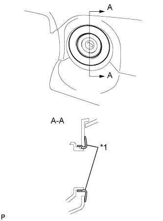
Text in Illustration *1
Instrument Panel Finish Plate
| 14. CONNECT HOOD LOCK CONTROL LEVER SUB-ASSEMBLY |
Engage the 3 claws and install the hood lock control lever.
| 15. CONNECT FUEL LID LOCK OPEN LEVER SUB-ASSEMBLY (for RHD) |
Engage the 3 claws and install the fuel lid lock open lever.
| 16. INSTALL NO. 1 INSTRUMENT PANEL REGISTER ASSEMBLY |
Engage the 4 clips and 2 claws and install the instrument panel register.
| 17. INSTALL FRONT DOOR OPENING TRIM WEATHERSTRIP |
Install the front door opening trim weatherstrip.
| 18. INSTALL COWL SIDE TRIM BOARD |
- HINT:
- Use the same procedure as for the RH side.
| 19. INSTALL FOOTREST CLIP (for LHD) |
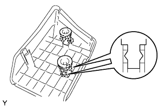 |
- HINT:
- Use the same procedure for both sides.
Engage the 2 claws and install the footrest clip.
| 20. INSTALL FRONT FLOOR FOOTREST (for LHD) |
Engage the 2 studs and install the front floor footrest.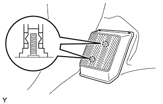
| 21. INSTALL FRONT DOOR SCUFF PLATE |
- HINT:
- Use the same procedure as for the RH side.