2011-2016 FJ Cruiser · Service Manual STEERING

REMOVAL

Removal / installation · Vehicles built Aug 2009 – Oct 2010

Versions by build date: Jul 2007 – Jul 2009 Aug 2009 – Oct 2010 from Nov 2010


1. DISCONNECT CABLE FROM NEGATIVE BATTERY TERMINAL

2. PLACE FRONT WHEELS FACING STRAIGHT AHEAD

3. REMOVE FRONT WHEELS

4. REMOVE NO. 1 ENGINE UNDER COVER SUB-ASSEMBLY

  1. A217571
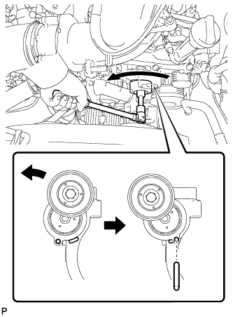
    While turning the belt tensioner counterclockwise, align the service hole for the belt tensioner and the belt tensioner fixing position, and then insert a bar of φ 6 mm (0.236 in.) into the service hole to fix the belt tensioner in place.

    HINT:
    The pulley bolt for the belt tensioner has a left-hand thread.

  1. Remove the V belt.


5. REMOVE REAR ENGINE UNDER COVER ASSEMBLY
  1. Remove the 4 bolts, then remove the rear engine under cover.


6. REMOVE NO. 2 EXHAUST FRONT PIPE ASSEMBLY

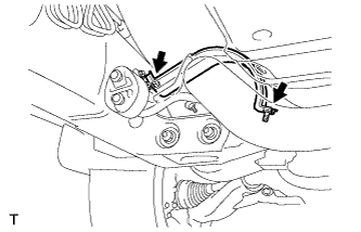
  1. A129939
    Remove the 2 bolts, then remove the exhaust pipe stopper bracket. (for 4WD)

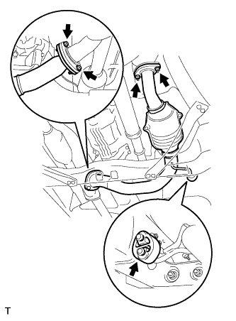
  1. A129938
    Remove the 2 bolts and 2 nuts and separate the exhaust pipe support, then remove the No. 2 front exhaust pipe.


7. REMOVE FRONT EXHAUST PIPE ASSEMBLY

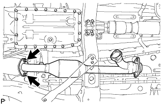
  1. A128851
    Remove the 2 nuts, then remove the front exhaust pipe.

  1. Remove the front exhaust pipe gasket.


8. REMOVE PROPELLER SHAFT HEAT INSULATOR

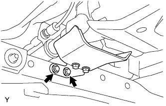
C133778
  1. Remove the 2 bolts and propeller shaft heat insulator.


9. REMOVE FRONT PROPELLER SHAFT ASSEMBLY

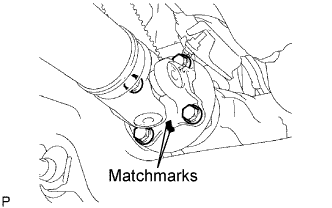
C098708E04
  1. Place matchmarks on the propeller shaft flange and differential flange.

  1. Remove the 4 nuts, 4bolts and 4 washers.

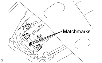
  1. C098709E03
    Place matchmarks on the propeller shaft flange and transfer flange.

  1. Remove the 4 nuts, 4 washers and the propeller shaft assembly.


10. REMOVE PROPELLER SHAFT ASSEMBLY

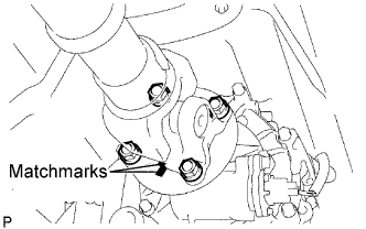
C098699E02
  1. Place matchmarks on the propeller shaft flange and transfer flange.

  1. Remove the 4 nuts and 4 washers.

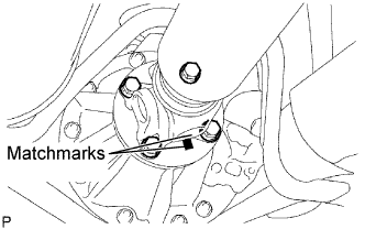
  1. C098700E02
    Place matchmarks on the propeller shaft flange and differential flange.

  1. Remove the 4 nuts, 4 bolts, 4 washers and the propeller shaft assembly.


11. REMOVE FRONT SUSPENSION MEMBER BRACKET LH

C129541
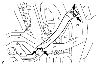
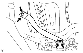
  1. Remove the 4 bolts and the front suspension member bracket LH.


12. REMOVE FRONT SUSPENSION MEMBER BRACKET RH

C129542
  1. Remove the 4 bolts and the front suspension member bracket RH.


13. REMOVE NO. 3 FRAME CROSSMEMBER SUB-ASSEMBLY

C135785
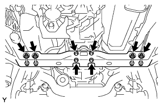
  1. Remove the 4 bolts from the No. 3 frame crossmember sub-assembly.

  1. Remove the 4 nuts and 4 bolts and remove the No. 3 frame crossmember sub-assembly.

14. REMOVE NO.2 STEERING INTERMEDIATE SHAFT SUB-ASSEMBLY

C137982
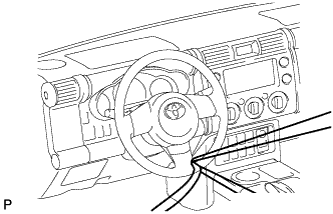
  1. Fix the steering wheel with the seat belt in order to prevent it from rotating.

    HINT:
    The operation is effective for preventing any damage to the spiral cable.

  1. F051677E01
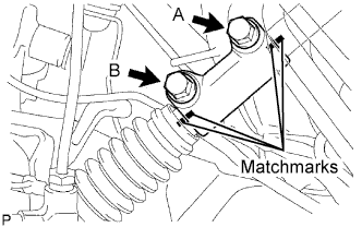
    Place matchmarks on the steering sliding yoke, No. 2 steering intermediate shaft and steering intermediate shaft.

  1. Remove bolts A and B from the steering sliding yoke.

  1. Slide the steering sliding yoke up and separate it from the No. 2 steering intermediate shaft.

  1. Pull down the steering sliding yoke from the steering intermediate shaft to remove it.

  1. F051678E02
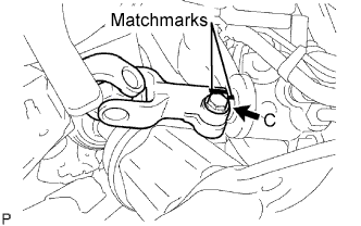
    Place matchmarks on the No. 2 steering intermediate shaft and power steering link.

  1. Remove bolt C from the No. 2 steering intermediate shaft.

  1. Slide the No. 2 steering intermediate shaft up and remove it from the power steering link.


15. SEPARATE TIE ROD END SUB-ASSEMBLY LH
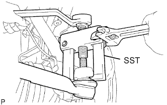
  1. Remove the cotter pin and nut.

  1. F051679E02
    Using SST, separate the tie rod end from the steering knuckle arm.
    SST
    09628-62011  


16. SEPARATE TIE ROD END SUB-ASSEMBLY RH

HINT:
The removal procedure for the RH side is the same as that for the LH side.


17. SEPARATE PRESSURE FEED TUBE ASSEMBLY

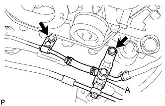
  1. C171935E01
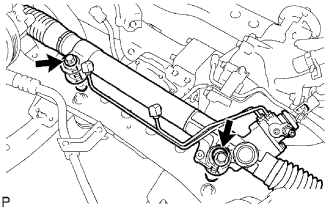
    Remove the 2 bolts and separate the tube support brackets.

    NOTICE:
    Ensure that A is not impacted during removal.

  1. F051682E03
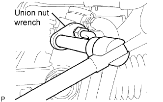
    Using union nut wrench, loosen the flare nut and separate the pressure feed tube.

  1. C171459
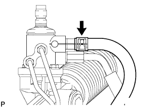
    Disengage the clip and disconnect the return hose.


18. REMOVE POWER STEERING LINK

F051684E01
  1. Remove the 2 bolts and 2 nuts.

    NOTICE:
    The nut has a detent, so never turn the nut. Be sure to turn only the bolt.

  1. Tilt the transmission and remove the power steering link.

← REMOVAL (Jul 2007 – Jul 2009)REMOVAL (from Nov 2010) →