REMOVAL
Removal / installation · Vehicles built from Nov 2010
Versions by build date: Jul 2007 – Jul 2009 Aug 2009 – Oct 2010 from Nov 2010
| 1.
PLACE FRONT WHEELS FACING STRAIGHT AHEAD |
|
| 2.
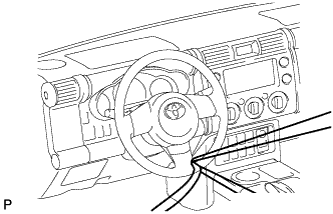
SECURE STEERING WHEEL |
 |
- Secure the steering wheel with the seat belt in order to prevent it from rotating.
- HINT:
- This operation is necessary to prevent damage to the spiral cable.
| 4.
REMOVE ENGINE ASSEMBLY |
|
(Click here)
| 5.
REMOVE NO. 2 STEERING INTERMEDIATE SHAFT SUB-ASSEMBLY
|
|
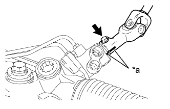
Put matchmarks on the No. 2 steering intermediate shaft sub-assembly and the power steering link.
Text in Illustration
*a
|
Matchmark
|
Remove the bolt and the No. 2 steering intermediate shaft sub-assembly from the power steering link.
| 6.
SEPARATE TIE ROD END SUB-ASSEMBLY LH
|
|
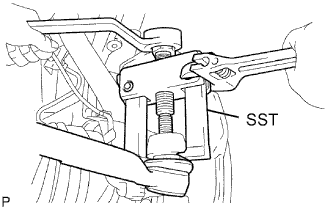
Remove the cotter pin and nut.
- Using SST, separate the tie rod end from the steering knuckle.
- SST
- 09628-62011
| 7.
SEPARATE TIE ROD END SUB-ASSEMBLY RH |
|
- HINT:
- Use the same procedure for the RH side as for the LH side.
| 8.
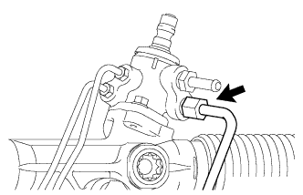
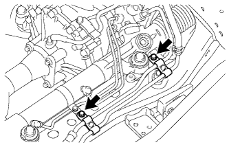
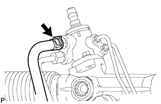
DISCONNECT PRESSURE FEED TUBE ASSEMBLY (for LHD) |
|
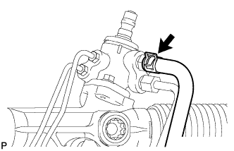
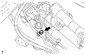
- Remove the clip and disconnect the pressure feed tube assembly (return tube side) from the power steering link assembly.
- Using a union nut wrench (17 mm), disconnect the pressure feed tube assembly (pressure feed tube side) from the power steering link assembly.
- Remove the 2 bolts and separate the pressure feed tube clamp.
| 9.
DISCONNECT RETURN TUBE SUB-ASSEMBLY (for RHD) |
|
- Remove the clip and disconnect the return tube sub-assembly from the power steering link assembly.
| 10.
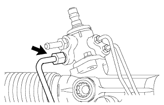
DISCONNECT NO. 1 PRESSURE FEED TUBE (for RHD) |
|
- Using a union nut wrench (17 mm), disconnect the No. 1 pressure feed tube from the power steering link assembly.
- Remove the bolt and separate the No. 1 pressure feed tube clamp.
| 11.
REMOVE POWER STEERING LINK ASSEMBLY |
|
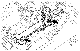
- Remove the 2 bolts, 2 nuts and the power steering link assembly.