INSTALLATION
Removal / installation · Vehicles built from Aug 2014
Versions by build date: Jul 2007 – Oct 2010 Nov 2010 – Jul 2014 from Aug 2014
| 1. INSTALL TRANSFER ASSEMBLY |

Install the transfer onto the transmission.
Install the 2 clamps and 8 bolts.
- Torque:
- 24 N*m{ 244 kgf*cm , 17 ft.*lbf }
| 2. INSTALL MANUAL TRANSMISSION CASE COVER SUB-ASSEMBLY (w/ Case Cover) |
Install the manual transmission case cover sub-assembly onto the manual transmission with the 5 bolts.
- Torque:
- 12 N*m{ 117 kgf*cm , 8 ft.*lbf }
| 3. INSTALL COLLAR (w/o Case Cover) |
Install the 2 collars onto the manual transmission with 2 bolts.
- Torque:
- 12 N*m{ 117 kgf*cm , 8 ft.*lbf }
| 4. INSTALL MANUAL TRANSMISSION WITH TRANSFER |
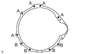  |
Install the manual transmission with transfer with the 9 bolts.
- Torque:
- for Bolt A:
- 71 N*m{ 724 kgf*cm , 52 ft.*lbf }
- for Bolt B:
- 37 N*m{ 377 kgf*cm , 27 ft.*lbf }
| 5. CONNECT WIRE HARNESS |
| 6. CONNECT CONNECTOR |
Connect the back-up light switch connector.
Connect the speedometer sensor connector.
Connect the 2 transfer indicator switch connectors.
| 7. INSTALL REAR NO. 1 ENGINE MOUNTING INSULATOR |
Install the rear No. 1 engine mounting insulator with the 4 bolts.
- Torque:
- 65 N*m{ 663 kgf*cm , 48 ft.*lbf }
| 8. INSTALL NO. 3 FRAME CROSSMEMBER SUB-ASSEMBLY |
Install the No. 3 frame crossmember sub-assembly with the 4 bolts and 4 nuts.
- Torque:
- 72 N*m{ 734 kgf*cm , 53 ft.*lbf }
Install the 4 bolts to the No. 3 frame crossmember sub-assembly.
- Torque:
- 30 N*m{ 306 kgf*cm , 22 ft.*lbf }
| 9. INSTALL FRONT SUSPENSION MEMBER BRACKET LH |
Install the front suspension member bracket LH with the 4 bolts.
- Torque:
- 33 N*m{ 337 kgf*cm , 24 ft.*lbf }
| 10. INSTALL FRONT SUSPENSION MEMBER BRACKET RH |
Install the front suspension member bracket RH with the 4 bolts.
- Torque:
- 33 N*m{ 337 kgf*cm , 24 ft.*lbf }
| 11. INSTALL CLUTCH RELEASE CYLINDER ASSEMBLY |
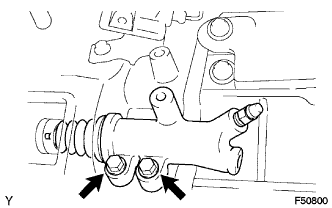 |
Install the clutch release cylinder with the 2 bolts.
- Torque:
- 12 N*m{ 120 kgf*cm , 9 ft.*lbf }
| 12. INSTALL CLUTCH ACCUMULATOR ASSEMBLY |
Install the clutch accumulator assembly with the 3 bolts.
- Torque:
- 12 N*m{ 120 kgf*cm , 9 ft.*lbf }
Temporarily tighten the flexible hose tube to the clutch accumulator assembly.
Install the clutch line bracket with the nut.
- Torque:
- 19 N*m{ 194 kgf*cm , 14 ft.*lbf }
Using a union nut wrench, fully tighten the flexible hose tube.
- Torque:
- for M10 flare nut:
- 15 N*m{ 155 kgf*cm , 11 ft.*lbf }
- for M12 flare nut:
- 20 N*m{ 199 kgf*cm , 14 ft.*lbf }
- NOTICE:
- Use the formula to calculate special torque values for situations where a union nut wrench is combined with a torque wrench (Click here).
Temporarily install the clutch release tube to the clutch accumulator assembly.
Install the clutch line bracket with the bolt.
- Torque:
- 12 N*m{ 120 kgf*cm , 9 ft.*lbf }
Using a union nut wrench, fully tighten the clutch release tube.
- Torque:
- 15 N*m{ 155 kgf*cm , 11 ft.*lbf }
- NOTICE:
- Use the formula to calculate special torque values for situations where a union nut wrench is combined with a torque wrench (Click here).
| 13. INSTALL ACCUMULATOR TO FLEXIBLE HOSE TUBE |
Install the flexible hose tube to the manual transmission with the 3 nuts.
- Torque:
- 19 N*m{ 194 kgf*cm , 14 ft.*lbf }
Using a union nut wrench (12 mm), connect the flexible hose tube to the clutch accumulator assembly.
- Torque:
- 20 N*m{ 199 kgf*cm , 14 ft.*lbf }
- NOTICE:
- Use the formula to calculate special torque values for situations where a union nut wrench is combined with a torque wrench (Click here).
Install the flexible hose with a new clip.
Using a union nut wrench (12 mm), connect the flexible hose tube to the flexible hose while holding the flexible hose with a wrench.
- Torque:
- 20 N*m{ 199 kgf*cm , 14 ft.*lbf }
- NOTICE:
- Use the formula to calculate special torque values for situations where a union nut wrench is combined with a torque wrench (Click here).
| 14. INSTALL NO. 1 CLUTCH HOUSING COVER |
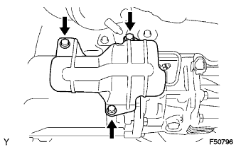 |
Install the No. 1 clutch housing cover with the 3 bolts.
- Torque:
- 12 N*m{ 120 kgf*cm , 9 ft.*lbf }
| 15. INSTALL FLYWHEEL HOUSING SIDE COVER |
Install the flywheel housing side cover onto the cylinder block.
| 16. INSTALL STARTER ASSEMBLY |
Install the starter with the 2 bolts.
- Torque:
- 37 N*m{ 377 kgf*cm , 27 ft.*lbf }
Connect the starter wire with the bolt and nut.
- Torque:
- for bolt:
- 8.0 N*m{ 82 kgf*cm , 71 in.*lbf }
- for nut:
- 9.8 N*m{ 100 kgf*cm , 87 in.*lbf }
Close the terminal cap.
Connect the starter connector.
Connect the ground wire with the bolt.
- Torque:
- 13 N*m{ 133 kgf*cm , 10 ft.*lbf }
| 17. INSTALL NO. 2 MANIFOLD STAY |
Install the No. 2 manifold stay to the exhaust manifold sub-assembly LH with the 3 bolts.
- Torque:
- 40 N*m{ 408 kgf*cm , 30 ft.*lbf }
| 18. INSTALL MANIFOLD STAY |
Install the manifold stay to the exhaust manifold sub-assembly RH with the 3 bolts.
- Torque:
- 40 N*m{ 408 kgf*cm , 30 ft.*lbf }
| 19. INSTALL PROPELLER SHAFT ASSEMBLY |
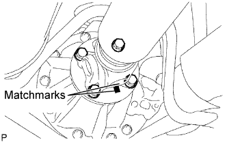 |
Align the matchmarks on the propeller shaft flange and differential flange.
Install the propeller shaft assembly with the 4 bolts, 4 nuts and 4 washers.
- Torque:
- 88 N*m{ 899 kgf*cm , 65 ft.*lbf }
Align the matchmarks on the propeller shaft flange and transfer flange.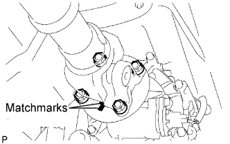
Install the propeller shaft assembly with the 4 nuts and 4 washers.
- Torque:
- 88 N*m{ 899 kgf*cm , 65 ft.*lbf }
| 20. INSTALL FRONT PROPELLER SHAFT ASSEMBLY |
Align the matchmarks on the yoke and differential flange.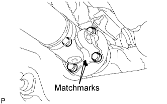
Install the propeller shaft assembly with the 4 bolts, 4 nuts and 4 washers.
- Torque:
- 88 N*m{ 899 kgf*cm , 65 ft.*lbf }
Align the matchmarks on the yoke and transfer flange.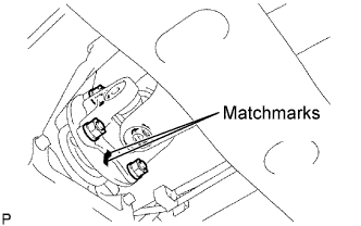
Install the propeller shaft assembly with the 4 nuts and 4 washers.
- Torque:
- 88 N*m{ 899 kgf*cm , 65 ft.*lbf }
| 21. INSTALL PROPELLER SHAFT HEAT INSULATOR |
Install the propeller shaft heat insulator with the 2 bolts.
- Torque:
- 16 N*m{ 160 kgf*cm , 12 ft.*lbf }
| 22. INSTALL FRONT EXHAUST PIPE ASSEMBLY |
Using a vernier caliper, measure the free length of the compression springs.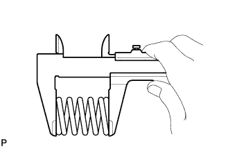
- Free Length of Compression Spring:
Transmission Type
Identification Color
Standard Length
Minimum Length
Manual Transmission
White
40.36 mm (1.58 in.)
38.86 mm (1.53 in.)
Automatic Transmission
Blue
43 mm (1.69 in.)
41.5 mm (1.63 in.)
Automatic Transmission
Pink
40 mm (1.57 in.)
38.5 mm (1.52 in.)
Automatic Transmission
None
42 mm (1.65 in.)
40.5 mm (1.59 in.)
By hand, insert a new gasket to the rear flange of the front exhaust pipe assembly.
Using a plastic hammer, place a wooden block against the gasket and gradually tap in the gasket all the way to the edge of the front exhaust pipe assembly flange.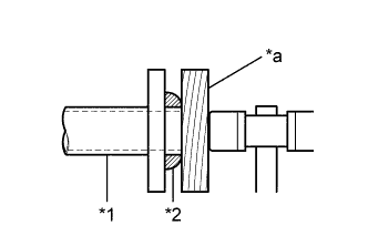
Text in Illustration *1
Front Exhaust Pipe Assembly
*2
Gasket
*a
Wooden Block
- NOTICE:
- Make sure that the gasket is in the correct direction when installing.
- Do not reuse the removed gasket.
- When installing the front exhaust pipe assembly, do not use the center exhaust pipe assembly to press in the gasket.
- Make sure that the gasket is in the correct direction when installing.
Install a new gasket to the front flange of the front exhaust pipe assembly.
Install the front exhaust pipe assembly to the exhaust manifold sub-assembly RH with 2 new nuts.
- Torque:
- 54 N*m{ 554 kgf*cm , 40 ft.*lbf }
Connect the front exhaust pipe assembly to the center exhaust pipe assembly with the 2 bolts and 2 compression springs.
- Torque:
- 43 N*m{ 438 kgf*cm , 32 ft.*lbf }
Connect the heated oxygen sensor connector.
| 23. INSTALL FRONT NO. 2 EXHAUST PIPE ASSEMBLY |
Install the 2 new gaskets to the front No. 2 exhaust pipe assembly.
Install the front No. 2 exhaust pipe assembly to the exhaust pipe support.
Connect the front No. 2 exhaust pipe assembly to the exhaust manifold sub-assembly LH with 2 new nuts.
- Torque:
- 54 N*m{ 554 kgf*cm , 40 ft.*lbf }
Connect the front No. 2 exhaust pipe assembly to the front exhaust pipe assembly with the 2 bolts.
- Torque:
- 48 N*m{ 489 kgf*cm , 35 ft.*lbf }
Connect the heated oxygen sensor connector.
| 24. INSTALL EXHAUST PIPE STOPPER BRACKET |
Install the exhaust pipe stopper bracket to the frame sub-assembly with the 2 bolts.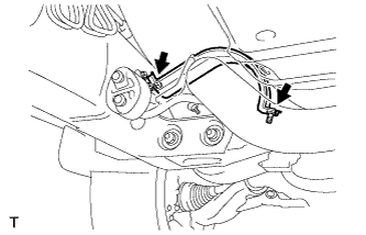
- Torque:
- 19 N*m{ 194 kgf*cm , 14 ft.*lbf }
| 25. ADD MANUAL TRANSMISSION OIL |
| 26. ADJUST MANUAL TRANSMISSION OIL |
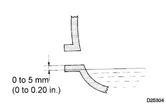 |
Park the vehicle in a level place.
Remove the transmission filler plug and gasket.
Check that the oil surface is within 5 mm (0.20 in.) of the lowest point of the transmission filler plug opening.
- NOTICE:
- Problems may occur when the oil level is too high or low.
- After replacing the oil, drive the vehicle and check the oil level again.
- Problems may occur when the oil level is too high or low.
Check for oil leakage when the oil level is low.
Install the transmission filler plug and a new gasket.
- Torque:
- 37 N*m{ 377 kgf*cm , 27 ft.*lbf }
| 27. INSTALL FLOOR SHIFT SHIFT LEVER ASSEMBLY |
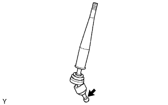 |
Apply MP grease to the tip of the shift lever.
Text in Illustration 
MP grease
Cover the shift lever cap with a cloth.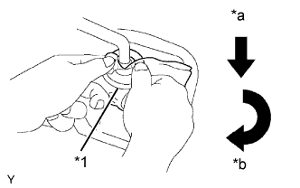
Text in Illustration *1
Cloth
*a
Down
*b
Clockwise
Pressing down on the shift lever cap, turn it clockwise to install the floor shift shift lever assembly.
| 28. REMOVE TRANSFER HIGH AND LOW SHIFT LEVER ASSEMBLY |
Install the transfer high and low shift lever assembly onto the shift lever retainer.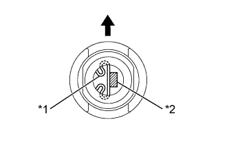
Text in Illustration *1
Select Return Spring
*2
Tip of Shift Lever
Front
Using needle-nose pliers, install the snap ring.
| 29. INSTALL SHIFT LEVER BOOT ASSEMBLY |
Install the shift lever boot assembly with the 4 screws and 2 clips.
| 30. INSTALL TRANSFER SHIFT LEVER KNOB SUB-ASSEMBLY |
Install the shift lever knob.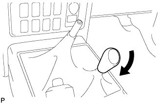
| 31. INSTALL TRANSMISSION SHIFT LEVER KNOB SUB-ASSEMBLY |
Install the shift lever knob.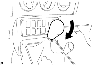
| 32. INSTALL FRONT CONSOLE BOX |
Engage the 5 guides and install the front console box.
Install the 4 <H> bolts.
| 33. INSTALL CONSOLE UPPER REAR PANEL SUB-ASSEMBLY |
Engage the 3 guides and 5 clips and install the console upper rear panel.
| 34. INSTALL PARKING BRAKE HOLE COVER SUB-ASSEMBLY |
Slide the parking brake hole cover toward the rear of the vehicle and engage the 2 guides.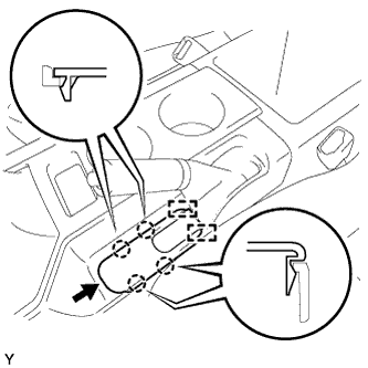
Engage the 4 claws and install the parking brake hole cover.
| 35. INSPECT FOR MANUAL TRANSMISSION OIL LEAK |
| 36. INSPECT FOR EXHAUST GAS LEAK |