INSTALLATION
Removal / installation · Vehicles built Jul 2007 – Oct 2010
Versions by build date: Jul 2007 – Oct 2010 Nov 2010 – Jul 2014 from Aug 2014
| 1.
INSTALL TRANSFER ASSEMBLY
|
 |
Install the transfer onto the transmission.
Install the 2 clamps and 8 bolts.
-
Torque:
- 24 N*m{
244 kgf*cm
, 17 ft.*lbf
}
| 2.
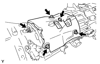
INSTALL MANUAL TRANSMISSION CASE COVER SUB-ASSEMBLY |
|
Install the manual transmission case cover with the 5 bolts.
-
Torque:
- 12 N*m{
117 kgf*cm
, 8 ft.*lbf
}
| 3.
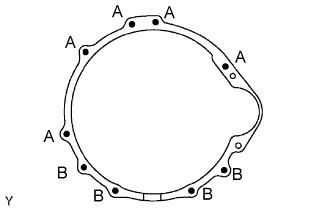
INSTALL MANUAL TRANSMISSION WITH TRANSFER |
|
Install the manual transmission with transfer with the 9 bolts.
-
Torque:
- 71 N*m{
724 kgf*cm
, 52 ft.*lbf
}
for bolt A
- 37 N*m{
377 kgf*cm
, 27 ft.*lbf
}
for bolt B
| 5.
CONNECT CONNECTOR |
|
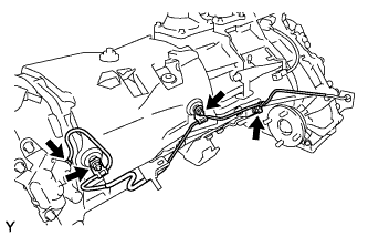
Connect the back-up light switch connector.
Connect the speedometer sensor connector.
Connect the 2 transfer indicator switch connectors.
| 6.
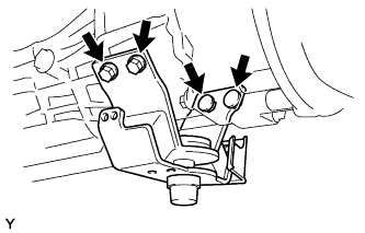
INSTALL REAR NO. 1 ENGINE MOUNTING INSULATOR |
|
Install engine mounting insulator rear No. 1 with the 4 bolts.
-
Torque:
- 65 N*m{
663 kgf*cm
, 48 ft.*lbf
}
| 7.
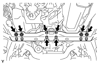
INSTALL NO. 3 FRAME CROSSMEMBER SUB-ASSEMBLY |
|
Install the No. 3 frame crossmember sub-assembly with the 4 bolts and 4 nuts.
-
Torque:
- 72 N*m{
734 kgf*cm
, 53 ft.*lbf
}
Install the No. 3 frame crossmember sub-assembly with the 4 bolts.
-
Torque:
- 30 N*m{
306 kgf*cm
, 22 ft.*lbf
}
| 8.
INSTALL FRONT SUSPENSION MEMBER BRACKET LH |
|
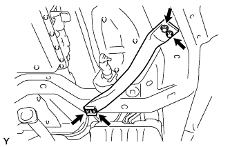
Install the front suspension member bracket LH with the 4 bolts.
-
Torque:
- 33 N*m{
337 kgf*cm
, 24 ft.*lbf
}
| 9.
INSTALL FRONT SUSPENSION MEMBER BRACKET RH |
|
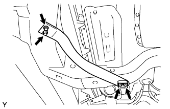
Install the front suspension member bracket RH with the 4 bolts.
-
Torque:
- 33 N*m{
337 kgf*cm
, 24 ft.*lbf
}
| 10.
INSTALL CLUTCH ACCUMULATOR ASSEMBLY
|
|
Install the clutch accumulator assembly with the 3 bolts.
-
Torque:
- 12 N*m{
120 kgf*cm
, 9 ft.*lbf
}
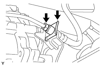
Temporarily tighten the flexible hose tube to the clutch accumulator assembly.
Install the clutch line bracket with the nut.
-
Torque:
- 19 N*m{
194 kgf*cm
, 14 ft.*lbf
}
Using a union nut wrench, fully tighten the flexible hose tube.
-
Torque:
- for M10 flare nut:
- 15 N*m{
155 kgf*cm
, 11 ft.*lbf
}
- for M12 flare nut:
- 20 N*m{
199 kgf*cm
, 14 ft.*lbf
}
- NOTICE:
- Use the formula to calculate special torque values for situations where a union nut wrench is combined with a torque wrench (Click here).
Temporarily install the clutch release tube to the clutch accumulator assembly.
Install the clutch line bracket with the bolt.
-
Torque:
- 12 N*m{
120 kgf*cm
, 9 ft.*lbf
}
Using a union nut wrench, fully tighten the clutch release tube.
-
Torque:
- 15 N*m{
155 kgf*cm
, 11 ft.*lbf
}
- NOTICE:
- Use the formula to calculate special torque values for situations where a union nut wrench is combined with a torque wrench (Click here).
| 11.
INSTALL ACCUMULATOR TO FLEXIBLE HOSE TUBE |
|
Using a union nut wrench, connect the hose tube. (for flexible hose side)
-
Torque:
- for M10 flare nut:
- 15 N*m{
155 kgf*cm
, 11 ft.*lbf
}
- for M12 flare nut:
- 20 N*m{
199 kgf*cm
, 14 ft.*lbf
}
- NOTICE:
- Use the formula to calculate special torque values for situations where a union nut wrench is combined with a torque wrench (Click here).
Install a new clip.
- Using a union nut wrench, connect the hose tube. (for accumulator side)
-
Torque:
- for M10 flare nut:
- 15 N*m{
155 kgf*cm
, 11 ft.*lbf
}
- for M12 flare nut:
- 20 N*m{
199 kgf*cm
, 14 ft.*lbf
}
- NOTICE:
- Use the formula to calculate special torque values for situations where a union nut wrench is combined with a torque wrench (Click here).
Install the 3 nuts and connect the hose tube.
-
Torque:
- 19 N*m{
194 kgf*cm
, 14 ft.*lbf
}
| 12.
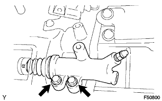
INSTALL CLUTCH RELEASE CYLINDER ASSEMBLY
|
|
Install the clutch release cylinder with the 2 bolts.
-
Torque:
- 12 N*m{
120 kgf*cm
, 9 ft.*lbf
}
| 13.
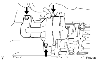
INSTALL NO. 1 CLUTCH HOUSING COVER
|
|
Install the No. 1 clutch housing cover with the 3 bolts.
-
Torque:
- 12 N*m{
120 kgf*cm
, 9 ft.*lbf
}
| 14.
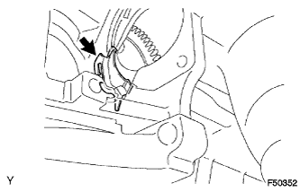
INSTALL FLYWHEEL HOUSING SIDE COVER |
|
Install the flywheel housing side cover onto the cylinder block.
| 15.
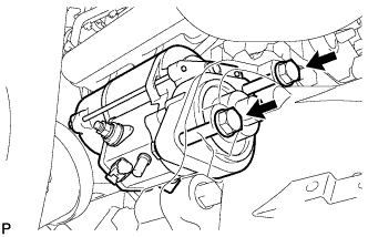
INSTALL STARTER ASSEMBLY
|
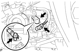
|
Install the starter assembly with 2 bolts.
-
Torque:
- 37 N*m{
377 kgf*cm
, 27 ft.*lbf
}
- Connect the wire harness to the terminal 30, then install the nut.
-
Torque:
- 5.9 N*m{
60 kgf*cm
, 52 in.*lbf
}
Connect the terminal 50 connector to the starter assembly.
| 16.
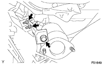
INSTALL MANIFOLD STAY |
|
Install the manifold stay with the 3 bolts.
-
Torque:
- 40 N*m{
408 kgf*cm
, 30 ft.*lbf
}
| 17.
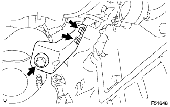
INSTALL NO. 2 MANIFOLD STAY |
|
Install the No. 2 manifold stay with the 3 bolts.
-
Torque:
- 40 N*m{
408 kgf*cm
, 30 ft.*lbf
}
| 18.
INSTALL PROPELLER SHAFT ASSEMBLY
|
|
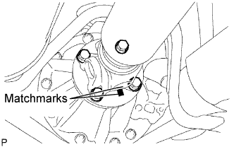
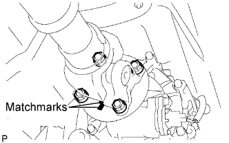
Align the matchmarks on the propeller shaft flange and differential flange.
Install the propeller shaft assembly with the 4 bolts, 4 nuts and 4 washers.
-
Torque:
- 88 N*m{
899 kgf*cm
, 65 ft.*lbf
}
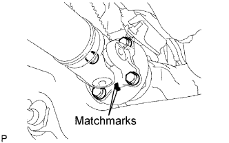
- Align the matchmarks on the propeller shaft flange and transfer flange.
Install the propeller shaft assembly with the 4 nuts and 4 washers.
-
Torque:
- 88 N*m{
899 kgf*cm
, 65 ft.*lbf
}
| 19.
INSTALL FRONT PROPELLER SHAFT ASSEMBLY
|
|
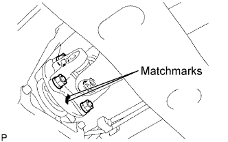
- Align the matchmarks on the yoke and differential flange.
Install the propeller shaft assembly with the 4 bolts, 4 nuts and 4 washers.
-
Torque:
- 88 N*m{
899 kgf*cm
, 65 ft.*lbf
}
- Align the matchmarks on the yoke and transfer flange.
Install the propeller shaft assembly with the 4 nuts and 4 washers.
-
Torque:
- 88 N*m{
899 kgf*cm
, 65 ft.*lbf
}
| 20.
INSTALL PROPELLER SHAFT HEAT INSULATOR |
|
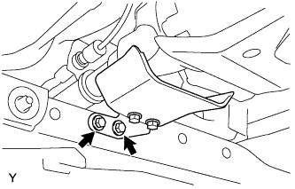
Install the propeller shaft heat insulator with the 2 bolts.
-
Torque:
- 16 N*m{
160 kgf*cm
, 12 ft.*lbf
}
| 21.
INSTALL FRONT EXHAUST PIPE ASSEMBLY
|
|
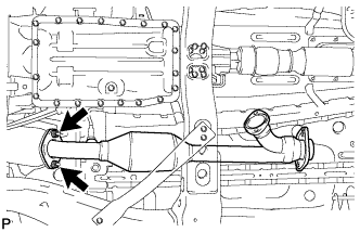
Install a new gasket onto the exhaust manifold RH.
- Install the exhaust front pipe with new 2 nuts.
-
Torque:
- 54 N*m{
554 kgf*cm
, 40 ft.*lbf
}
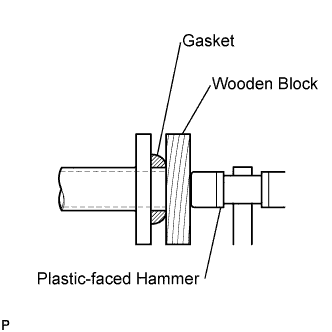
- Install a new gasket onto the front exhaust pipe.
Using a wooden block and plastic-faced hammer, tap in a new gasket until it is flush with the front exhaust pipe end.
- NOTICE:
- Make sure that the gasket is in the correct direction when installing.
- Do not reuse the removed gasket.
- Do not push in the gasket with the exhaust pipe when connecting it.
| 22.
INSTALL NO. 2 FRONT EXHAUST PIPE ASSEMBLY
|
|
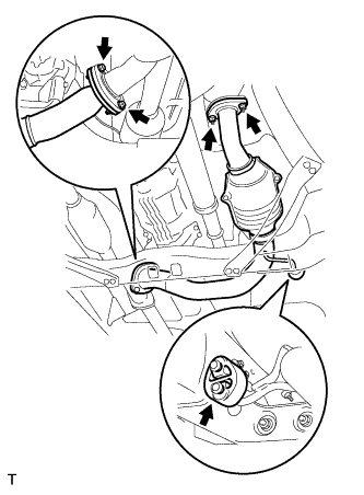
Install a new gasket onto the exhaust manifold LH.
Install a new gasket onto the No. 2 front exhaust pipe.
- Install the No. 2 front exhaust pipe with 2 new nuts and 2 bolts and exhaust pipe support.
-
Torque:
- Nut:
- 54 N*m{
554 kgf*cm
, 40 ft.*lbf
}
- Bolt:
- 48 N*m{
489 kgf*cm
, 35 ft.*lbf
}
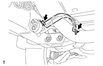
- Install the exhaust pipe stopper bracket with the 2 bolts (for 4WD).
-
Torque:
- 19 N*m{
193 kgf*cm
, 14 ft.*lbf
}
| 23.
ADD MANUAL TRANSMISSION OIL |
|
| 24.
ADJUST MANUAL TRANSMISSION OIL
|
|
Park the vehicle in a level place.
Remove the transmission filler plug and gasket.
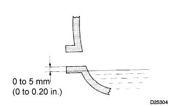
Check that the oil surface is within 5 mm (0.20 in.) of the lowest point of the transmission filler plug opening.
- NOTICE:
- Problems may occur when the oil level is too high or low.
- After replacing the oil, drive the vehicle and check the oil level again.
Check for oil leakage when the oil level is low.
Install the transmission filler plug and a new gasket.
-
Torque:
- 37 N*m{
377 kgf*cm
, 27 ft.*lbf
}
| 25.
INSTALL FLOOR SHIFT SHIFT LEVER ASSEMBLY |
|
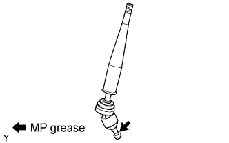
Apply MP grease to the tip of the shift lever.
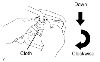
- Cover the shift lever cap with a cloth.
Pressing down on the shift lever cap, turn it clockwise to install the shift lever.
| 26.
REMOVE TRANSFER HIGH AND LOW SHIFT LEVER ASSEMBLY |
|
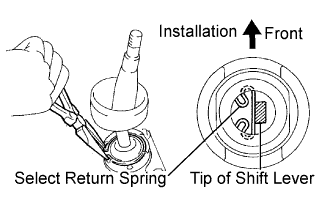
Install the transfer shift lever onto the shift lever retainer.
Using needle-nose pliers, install the snap ring.
| 27.
INSTALL SHIFT LEVER BOOT ASSEMBLY |
|
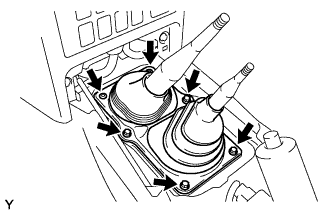
Install the shift lever boot with the 4 screws and 2 clips.
| 28.
INSTALL SHIFT LEVER KNOB SUB-ASSEMBLY (for Manual transmission) |
|
| 29.
INSTALL SHIFT LEVER KNOB SUB-ASSEMBLY (for Transfer) |
|
| 30.
INSTALL FRONT CONSOLE BOX
|
|
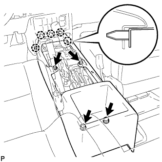
- Engage the 5 claws and install the front console box.
Install the 4 <D> screws.
| 31.
INSTALL CONSOLE UPPER REAR PANEL SUB-ASSEMBLY
|
|
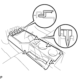
- Engage the 3 claws and 5 clips and install the console upper rear panel.
| 32.
INSTALL PARKING BRAKE HOLE COVER SUB-ASSEMBLY
|
|
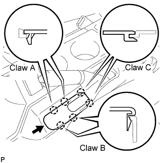
Slide the parking brake hole cover toward the rear of the vehicle and engage the 2 C claws.
Engage the 4 claws and install the parking brake hole cover.
| 33.
CONNECT CABLE TO NEGATIVE BATTERY TERMINAL |
|
-
Torque:
- 3.9 N*m{
40 kgf*cm
, 35 in.*lbf
}
| 34.
CHECK FOR EXHAUST GAS LEAKAGE |
|