REMOVAL
Removal / installation · Vehicles built from Aug 2014
Versions by build date: Jul 2007 – Oct 2010 Nov 2010 – Jul 2014 from Aug 2014
| 1.
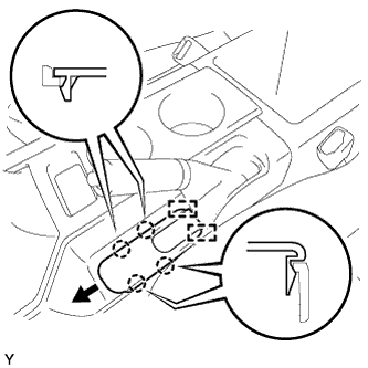
REMOVE PARKING BRAKE HOLE COVER SUB-ASSEMBLY
|
 |
- Disengage the 4 claws.
Slide the parking brake hole cover toward the front of the vehicle, disengage the 2 guides and remove the parking brake hole cover.
| 2.
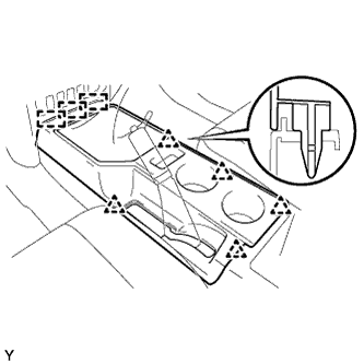
REMOVE CONSOLE UPPER REAR PANEL SUB-ASSEMBLY
|
|
- Shift the shift lever into the N position.
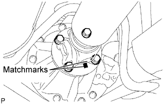
Disengage the 5 clips and 3 guides and remove the console upper rear panel.
| 3.
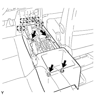
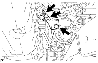
REMOVE FRONT CONSOLE BOX
|
|
- Remove the 4 <H> bolts.
Disengage the 5 guides and remove the console box.
| 4.
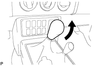
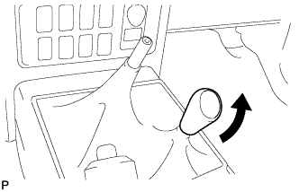
REMOVE TRANSMISSION SHIFT LEVER KNOB SUB-ASSEMBLY
|
|
- Remove the shift lever knob.
| 5.
REMOVE TRANSFER SHIFT LEVER KNOB SUB-ASSEMBLY
|
|
- Remove the shift lever knob.
| 6.
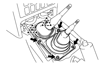
REMOVE SHIFT LEVER BOOT ASSEMBLY |
|
Remove the 4 screws, 2 clips and the shift lever boot assembly.
| 7.
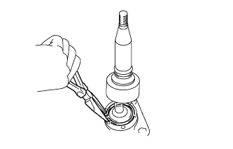
REMOVE TRANSFER HIGH AND LOW SHIFT LEVER ASSEMBLY |
|
Separate the shift lever cap boot from the transfer.
Using needle-nose pliers, remove the snap ring and pull out the transfer high and low shift lever assembly from the shift lever retainer.
| 8.
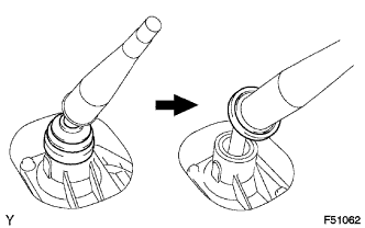
REMOVE FLOOR SHIFT SHIFT LEVER ASSEMBLY |
|
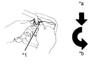
- Separate the shift lever cap boot from the manual transmission.
- Cover the shift lever cap with a cloth.
Pressing down on the shift lever cap, turn it counterclockwise to remove the floor shift shift lever assembly.
Text in Illustration
*1
|
Cloth
|
*a
|
Down
|
*b
|
Counterclockwise
|
Pull out the floor shift shift lever assembly.
| 9.
DRAIN MANUAL TRANSMISSION OIL |
|
Remove the drain plug and gasket and then drain the manual transmission oil.
Install a new gasket and drain plug.
-
Torque:
- 37 N*m{
377 kgf*cm
, 27 ft.*lbf
}
| 10.
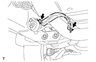
REMOVE EXHAUST PIPE STOPPER BRACKET
|
|
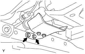
- Remove the 2 bolts, then remove the exhaust pipe stopper bracket.
| 11.
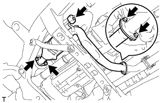
REMOVE FRONT NO. 2 EXHAUST PIPE ASSEMBLY
|
|
Disconnect the heated oxygen sensor connector.
- Remove the 2 bolts and disconnect the front No. 2 exhaust pipe assembly from the front exhaust pipe assembly.
Remove the 2 nuts and disconnect the front No. 2 exhaust pipe assembly from the exhaust manifold sub-assembly LH.
Remove the front No. 2 exhaust pipe assembly to the exhaust pipe support.
Remove the 2 gaskets from the front No. 2 exhaust pipe assembly.
| 12.
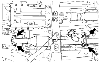
REMOVE FRONT EXHAUST PIPE ASSEMBLY
|
|
Disconnect the heated oxygen sensor connector.
- Remove the 2 bolts and 2 compression springs and disconnect the front exhaust pipe assembly from the center exhaust pipe assembly.
Remove the 2 nuts and front exhaust pipe assembly from the exhaust manifold sub-assembly RH.
Remove the 2 gaskets from the front exhaust pipe assembly.
| 13.
REMOVE PROPELLER SHAFT HEAT INSULATOR |
|
Remove the 2 bolts and the propeller shaft heat insulator.
| 14.
REMOVE FRONT PROPELLER SHAFT ASSEMBLY
|
|
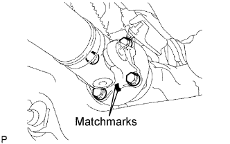
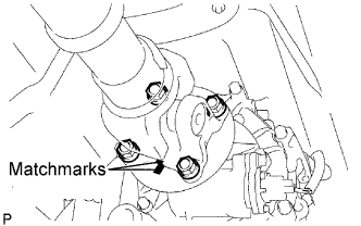
Place matchmarks on the propeller shaft flange and differential flange.
Remove the 4 nuts, 4bolts and 4 washers.
- Place matchmarks on the propeller shaft flange and transfer flange.
Remove the 4 nuts, 4 washers and the propeller shaft assembly.
| 15.
REMOVE PROPELLER SHAFT ASSEMBLY
|
|
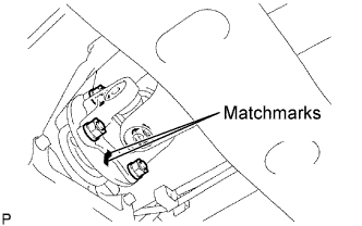
Place matchmarks on the propeller shaft flange and transfer flange.
Remove the 4 nuts and 4 washers.
- Place matchmarks on the propeller shaft flange and differential flange.
Remove the 4 nuts, 4 bolts, 4 washers and the propeller shaft assembly.
| 16.
REMOVE MANIFOLD STAY
|
|
- Remove the 3 bolts and manifold stay from the exhaust manifold sub-assembly RH.
| 17.
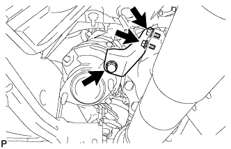
REMOVE NO. 2 MANIFOLD STAY
|
|
- Remove the 3 bolts and No. 2 manifold stay from the exhaust manifold sub-assembly LH.
| 18.
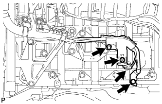
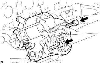
REMOVE STARTER ASSEMBLY
|
|
- Remove the bolt and ground wire.
Disconnect the starter connector.
Open the terminal cap.
Remove the nut and bolt, and then disconnect the starter wire.
- Remove the 2 bolts and starter.
| 19.
REMOVE FLYWHEEL HOUSING SIDE COVER |
|
- Remove the flywheel housing side cover from the cylinder block.
| 20.
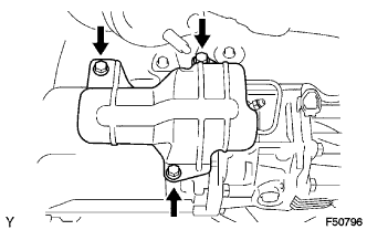
REMOVE NO. 1 CLUTCH HOUSING COVER
|
|
Remove the 3 bolts and No. 1 clutch housing cover.
| 21.
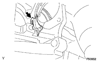
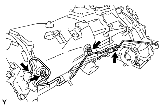
REMOVE ACCUMULATOR TO FLEXIBLE HOSE TUBE |
|
- Using a union nut wrench (12 mm), disconnect the flexible hose tube from the flexible hose while holding the flexible hose with a wrench.
Remove the clip and separate the flexible hose.
- Using a union nut wrench (12 mm), disconnect the flexible hose tube from the clutch accumulator assembly.
Remove the 3 nuts and the flexible hose tube.
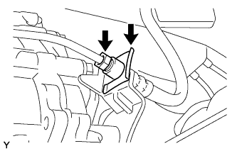
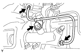
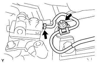
| 22.
REMOVE CLUTCH ACCUMULATOR ASSEMBLY
|
|
Using a union nut wrench, disconnect the clutch release tube from the clutch accumulator assembly.
- HINT:
- Use a container to catch the fluid.
Remove the bolt and clutch release tube.
- Using a union nut wrench, disconnect the flexible hose tube from the clutch accumulator assembly.
Remove the nut and clutch line bracket.
- Remove the 3 bolts and clutch accumulator assembly.
| 23.
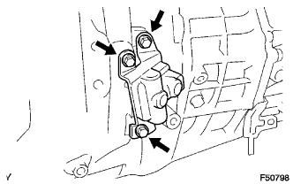
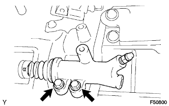
REMOVE CLUTCH RELEASE CYLINDER ASSEMBLY
|
|
Remove the 2 bolts and pull out the clutch release cylinder.
| 24.
SUPPORT MANUAL TRANSMISSION WITH TRANSFER |
|
Support the manual transmission with a transmission jack.
| 25.
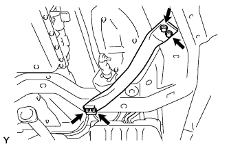
REMOVE FRONT SUSPENSION MEMBER BRACKET LH |
|
Remove the 4 bolts and the front suspension member bracket LH.
| 26.
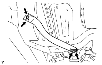
REMOVE FRONT SUSPENSION MEMBER BRACKET RH |
|
Remove the 4 bolts and the front suspension member bracket RH.
| 27.
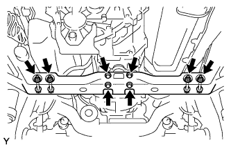
REMOVE NO. 3 FRAME CROSSMEMBER SUB-ASSEMBLY |
|
Remove the 4 bolts from the No. 3 frame crossmember sub-assembly.
Remove the 4 nuts, 4 bolts and the No. 3 frame crossmember sub-assembly.
| 28.
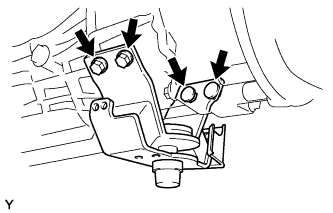
REMOVE REAR NO. 1 ENGINE MOUNTING INSULATOR |
|
Remove the 4 bolts and the rear No .1 engine mounting insulator from the manual transmission.
| 29.
DISCONNECT CONNECTOR |
|
Tilt down the manual transmission.
Disconnect the 2 transfer indicator switch connectors.
Disconnect the speedometer sensor connector.
Disconnect the back-up light switch connector.
| 30.
DISCONNECT WIRE HARNESS |
|
| 31.
REMOVE MANUAL TRANSMISSION WITH TRANSFER |
|
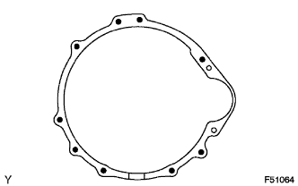
Remove the 9 bolts and the manual transmission.
| 32.
REMOVE MANUAL TRANSMISSION CASE COVER SUB-ASSEMBLY (w/ Case Cover) |
|
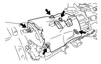
- Remove the 5 bolts and the manual transmission case cover sub-assembly.
| 33.
REMOVE COLLAR (w/o Case Cover) |
|
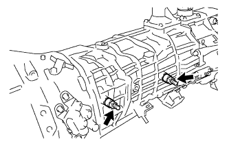
- Remove the 2 bolts and the 2 collars.
| 34.
REMOVE TRANSFER ASSEMBLY
|
|
Remove the 8 bolts and 2 clamps.
Remove the transfer from the transmission.