Versions by build date: Jul 2007 – Jul 2009from Aug 2009
1.
REMOVE VALVE GUIDE BUSH
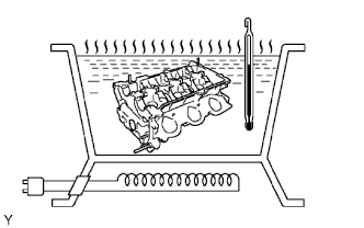
Gradually heat the cylinder head to 80 to 100°C (176 to 212°F).
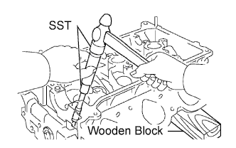
Place the cylinder head on a wooden block.
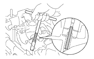
Using SST, tap out the valve guide bush.
SST
09201-10000 09201-01055 09950-70010
(09951-07100)
2.
INSTALL VALVE GUIDE BUSH
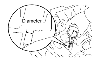
Using a caliper gauge, measure the bush bore diameter of the cylinder head.
Bush bore diameter:
10.295 to 10.315 mm (0.4053 to 0.4061 in.)
If the bush bore diameter of the cylinder head is greater than 10.315 mm (0.4061 in.), machine the bush bore to the dimension of 10.345 to 10.365 mm (0.4073 to 0.4081 in.).
Valve guide bush diameter:
Item
mm (in.)
STD
10.333 to 10.344 (0.4068 to 0.4072)
O/S 0.05
10.383 to 10.394 (0.4088 to 0.4092)
Gradually heat the cylinder head to 80 to 100°C (176 to 212°F).
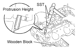
Place the cylinder head on a wooden block.
Using SST, tap in a new valve guide bush to the specified protrusion height.
SST
09201-10000 09201-01055 09950-70010
(09951-07100)
Protrusion height:
9.3 to 9.7 mm (0.366 to 0.382 in.)
Using a sharp 5.5 mm reamer, ream the valve guide bush to the standard specified clearance between the valve guide bush and valve stem.