INSPECTION
Inspection · Vehicles built Jul 2007 – Jul 2009
| INSPECT CAMSHAFTS |

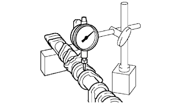  |
Inspect the camshaft for runout.
Place the camshaft on V-blocks.
Using a dial indicator, measure the circle runout at the center journal.
- Maximum runout:
- 0.06 mm (0.0024 in.)
Inspect the cam lobes.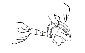
Using a micrometer, measure the cam lobe height.
- Standard cam lobe height:
- Intake:
- 44.168 to 44.268 mm (1.7389 to 1.7428 in.)
- Exhaust:
- 44.580 to 44.680 mm (1.7551 to 1.7591 in.)
- Minimum cam lobe height:
- Intake:
- 44.018 mm (1.7330 in.)
- Exhaust:
- 44.430 mm (1.7492 in.)
Inspect the camshaft journals.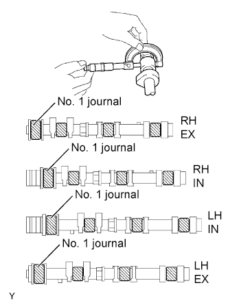
Using a micrometer, measure the journal diameter.
- No. 1 journal diameter:
- 35.971 to 35.985 mm (1.4162 to 1.4167 in.)
- Other journal diameters:
- 22.959 to 22.975 mm (0.9039 to 0.9045 in.)
| INSPECT CAMSHAFT TIMING GEAR ASSEMBLY |
Fix the intake camshaft in a vise.
- NOTICE:
- Be careful not to damage the camshaft.
Align the knock pin hole in the camshaft timing gear assembly with the knock pin of the camshaft, and install the camshaft timing gear assembly with the bolt.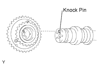
- Torque:
- 100 N*m{ 1020 kgf*cm , 74 ft.*lbf }
Confirm that the camshaft timing gear assembly is locked.
Release that lock pin.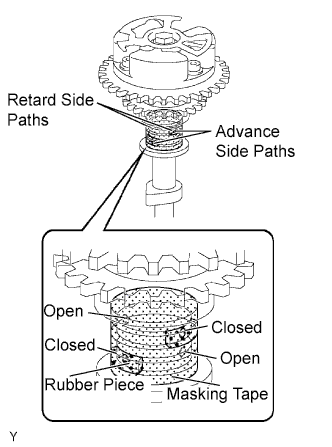
Cover the 4 oil paths of the cam journal with masking tape as shown in the illustration.
- HINT:
- One of the 2 grooves on the cam journal is for the retard side path (upper) and the other is for the advance side path (lower). Each groove has 2 oil paths. Plug one of the oil paths for each groove with a piece of rubber before wrapping the cam journal with tape.
Puncture the tape covering the advance oil path and retard oil path on the opposite side of the groove as shown in the illustration.
Apply compressed air at 200 kPa (2.0 kgf/cm2) into the 2 broken paths (the advance side path and the retard side path).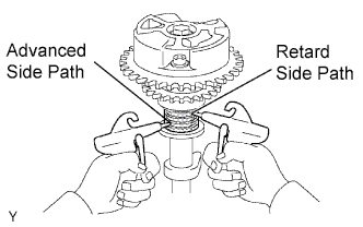
- NOTICE:
- Cover the paths with a shop rag or piece of cloth to avoid oil splashes.
Confirm that the camshaft timing gear assembly rotates in the timing advance direction when reducing the compressed air on the timing retard path.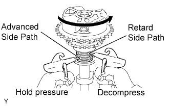
- HINT:
- When the lock pin is released, the camshaft timing gear rotates in the advance direction.
When the camshaft timing gear comes to the most advanced position, release the compressed air on the timing retard side path, and release that on the timing advance side path.
- NOTICE:
- Camshaft timing assembly gear occasionally shifts to the retard side abruptly if the air compression on the advanced side path is released first. This often causes breakage of the lock pin.
Check the smooth revolution.
Rotate the camshaft timing gear several times within the movable range except for the most retarded position and check it rotates smoothly.
- Standard:
- Moves smoothly in a range of about 31°
- NOTICE:
- Be sure to perform this check by hand, instead of using compressed air.
Check that the lock is in the most retarded position.
Confirm that the camshaft timing gear assembly is locked in the most retarded position.
Remove the set bolt, then remove the camshaft timing gear assembly.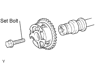
- NOTICE:
- Do not remove the other 3 bolts.