REASSEMBLY
Removal / installation · Vehicles built Jul 2007 – Jul 2009
Versions by build date: Jul 2007 – Jul 2009 from Aug 2009
| 1.
INSTALL RING PIN |
 |
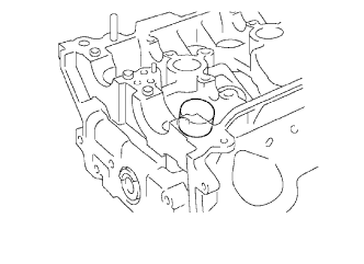
Using a plastic-faced hammer, tap in new ring pins to the specified protrusion height.
- Specified protrusion height:
- 2.7 to 3.3 mm (0.106 to 0.130 in.)

| 2.
INSTALL STRAIGHT PIN |
|
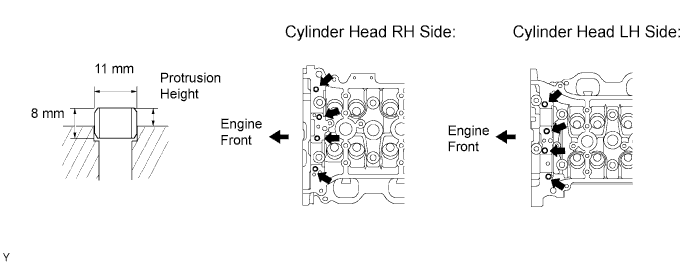
Using a plastic-faced hammer, tap in new straight pins to the specified protrusion height.
- Specified protrusion height:
Pin
|
Specification
|
A
|
17.5 to 19.5 mm (0.689 to 0.768 in.)
|
B
|
7.5 to 8.5 mm (0.295 to 0.335 in.)
|
C
|
7.0 to 9.0 mm (0.276 to 0.354 in.)
|
| 3.
INSTALL STUD BOLT |
|
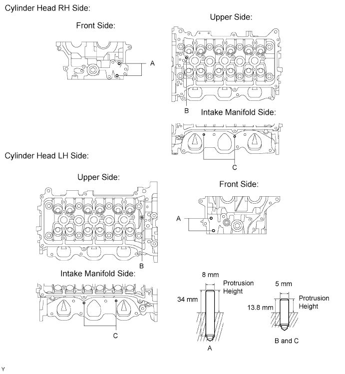
Using "Torx" socket wrench E5 and E7, install the stud bolts.
-
Torque:
- Stud bolt A:
- 4.0 N*m{
41 kgf*cm
, 35 in.*lbf
}
- Stud bolt B:
- 9.0 N*m{
92 kgf*cm
, 80 in.*lbf
}
- Stud bolt C:
- 4.0 N*m{
41 kgf*cm
, 35 in.*lbf
}
| 4.
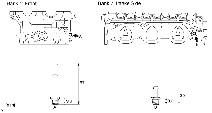
INSTALL UNION |
|
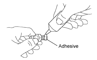
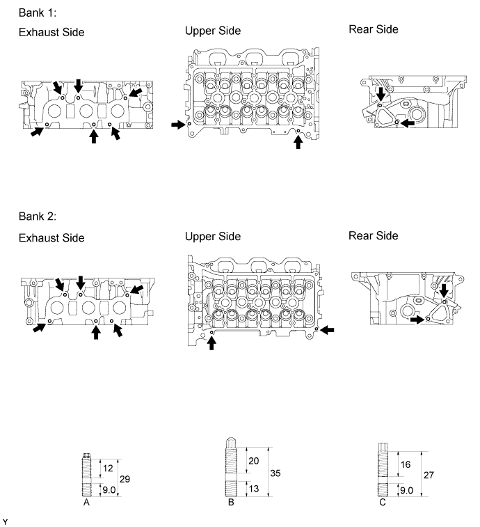
Apply adhesive to 2 or 3 threads of the bolt end.
- Adhesive:
- Toyota Genuine Adhesive 1324, Three Bond 1324 or the equivalent
Using a deep socket wrench 12, install the unions.
-
Torque:
- 15 N*m{
150 kgf*cm
, 11 ft.*lbf
}
| 5.
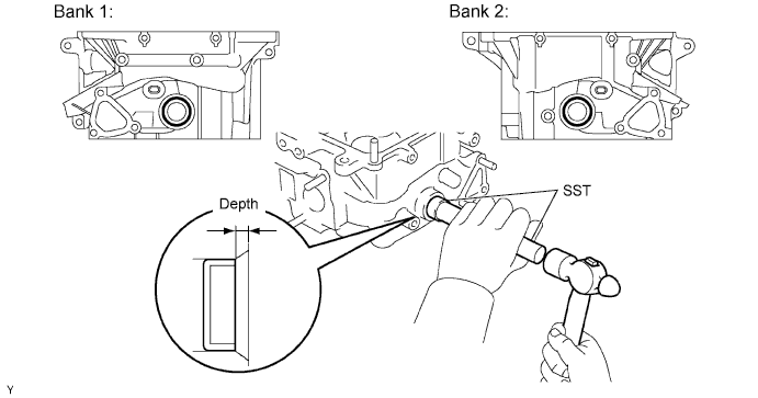
INSTALL TIGHT PLUG |
|
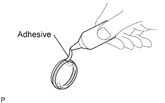
Apply adhesive around the new tight plugs.
Using SST, tap in the tight plugs to the specified depth.
- SST
- 09950-60010
(09951-00250)
09950-70010
(09951-07150)
- Specified depth:
- 1.5 mm (0.059 in.)
| 6.
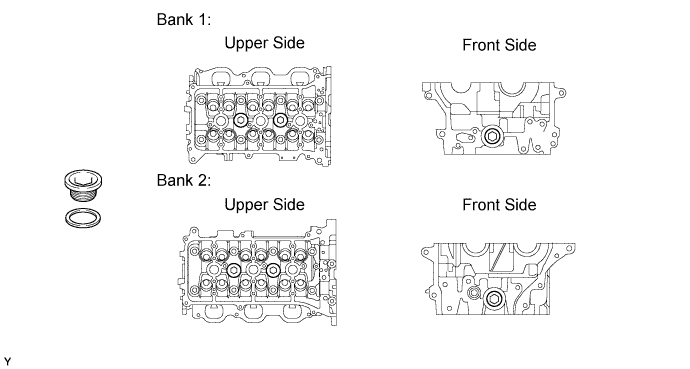
INSTALL WITH HEAD STRAIGHT SCREW PLUG |
|
Using a straight hexagon wrench 14, install a new gasket and straight screw plug.
-
Torque:
- 80 N*m{
816 kgf*cm
, 59 ft.*lbf
}
| 7.
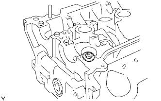
INSTALL VALVE STEM OIL O SEAL OR RING |
|
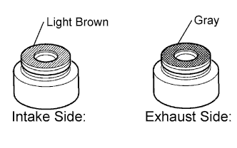
- HINT:
- The intake valve stem oil seal is light brown and the exhaust valve stem oil seal is gray.
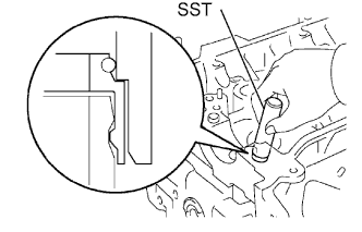
Apply a light coat of engine oil to the valve guide bush.
- Using SST, push in a new valve stem oil seal.
- SST
- 09201-41020
| 8.
INSTALL VALVE SPRING SEAT |
|
| 9.
INSTALL VALVE |
|
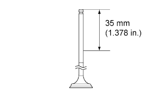
Apply engine oil to the valve as shown in the illustration.
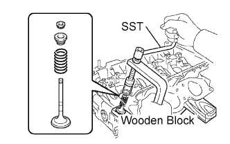
- Place the cylinder head on a wooden block.
Install the valve, inner compression spring and valve spring retainer.
Using SST, compress the inner compression spring and place the 2 valve spring retainer locks around the valve stem.
- SST
- 09202-70020
(09202-00010)
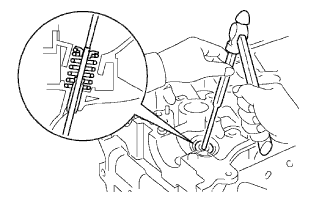
- Using a pin punch 5, lightly tap the valve stem tip to ensure a proper fit.
- NOTICE:
- Be careful not to damage the valve stem tip.
| 10.
INSTALL VALVE LIFTER |
|
Apply engine oil to the valve stem end and valve lifter, and install the valve lifter onto the valve stem.
Check that the valve lifter rotates smoothly by hand.