Entire Combination Meter does not Operate
Circuit diagnosis · Vehicles built Jul 2007 – Oct 2010
Versions by build date: Jul 2007 – Oct 2010 from Nov 2010
DESCRIPTION
This circuit provides power to the combination meter assembly.WIRING DIAGRAM
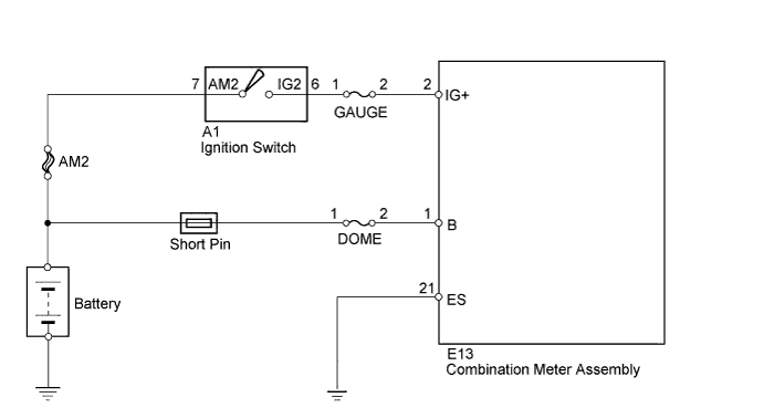

INSPECTION PROCEDURE
| 1. CHECK FUSES (DOME, GAUGE) |
 |
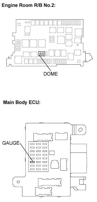
- Remove the DOME fuse from engine room relay block No. 2.
Remove the GAUGE fuse from the main body ECU.
Measure the resistance.
- Standard Resistance:
- Below 1Ω
Reinstall the fuse.
|
NG |
 |
|
|
|
| OK |
|
 |
|
| 2. INSPECT COMBINATION METER ASSEMBLY |
|
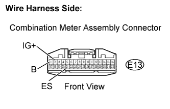
Disconnect the E13 combination meter connector.
Measure the resistance.
- Standard resistance:
Terminal No.
|
Condition
|
Specified Condition
|
E13-21 (ES) - Body ground
|
Always
|
Below 1 Ω
|
Measure the voltage.
- Standard voltage:
Terminal No.
|
Condition
|
Specified Condition
|
E13-2 (IG+) - Body ground
|
Ignition switch ON
|
11 to 14V
|
E13-1 (B) - Body ground
|
Always
|
11 to 14V
|
Reconnect the combination meter connector.
|
NG |
|
|
| REPAIR OR REPLACE HARNESS AND CONNECTOR |
|
|
| OK |
|
 |
|
|