P0722 Output Speed Sensor Circuit No Signal
Diagnostic trouble codes · Vehicles built Jul 2007 – Jul 2009
Versions by build date: Jul 2007 – Jul 2009 from Aug 2009
DESCRIPTION
The speed sensor SP2 detects the rotation speed of the transmission output shaft and sends signals to the ECM. The ECM determines the vehicle speed based on these signals. An AC voltage is generated in the speed sensor SP2 coil as the parking gear mounted on the rear planetary gear assembly rotates, and this voltage is sent to the ECM. The parking gear on the rear planetary gear is used as the timing rotor for this sensor. The gear shift point and lock-up timing are controlled by the ECM based on the signals from the vehicle speed sensor and the throttle position sensor.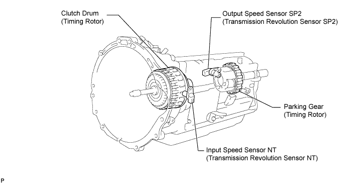

| DTC No. |
DTC Detection Conditions |
Trouble Areas |
| P0722 |
All conditions below are detected 5 seconds or more continuously. (2-trip detection logic)
|
|
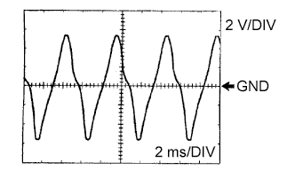
Check the waveform between terminals SP2+ and SP2- of the ECM connector.
- Standard:
- Refer to the illustration.
Item
Condition
Terminal
SP2+ - SP2-
Tool setting
2 V/DIV, 2 ms/DIV
Vehicle condition
Vehicle speed 20 km/h (12 mph)
MONITOR DESCRIPTION
The output speed sensor monitors the output shaft speed. The ECM controls the gearshift point and the lock up timing based on the signals from the output speed sensor and throttle position sensor.If the ECM detects no signal from the output shaft speed sensor even while the vehicle is moving, it will conclude that there is a malfunction in the output speed sensor. The ECM will illuminate the MIL and set the DTC.
WIRING DIAGRAM
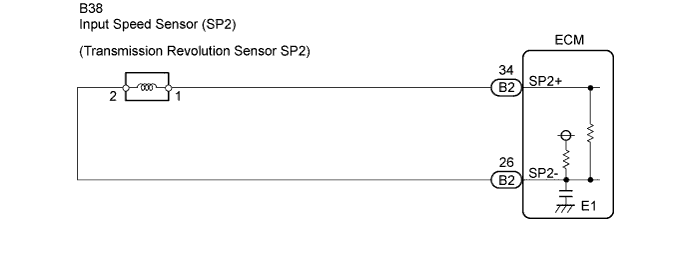
INSPECTION PROCEDURE
- HINT:
- According to the Data List displayed on a intelligent tester, you can read the values of components, such as the switches, sensors and actuators, without removing any parts. Reading the Data List as a first step of troubleshooting is one method of shortening labor time.
- NOTICE:
- In the table below, the values listed under "Normal Condition" are for reference only. Do not depend solely on these reference values when judging whether a part is faulty or not.
- Turn the ignition switch to OFF.
- Connect the intelligent tester to the DLC3.
- Turn the ignition switch to ON.
- Turn the tester ON.
- Enter the following menus: Powertrain / Engine and ECT / Data List.
- According to the display on the tester, read the Data List.
Tester Display
Measurement Item/Range
Normal Condition
Diagnostic Note
SPD (SP2)
Output shaft speed/
min.: 0 km/h (0 mph)
max.: 255 km/h (158 mph)
Vehicle stopped: 0 km/h (0 mph)
-
- HINT:
- SPD (SP2) is always 0 while driving:
Open or short in the sensor or circuit.
- The SPD (SP2) value displayed on the tester is much lower than the actual vehicle speed:
Sensor trouble, improper installation, or intermittent connection trouble of the circuit.
- SPD (SP2) is always 0 while driving:
| 1. INSPECT SPEED SENSOR (SP2) INSTALLATION |

Check the speed sensor (SP2) installation.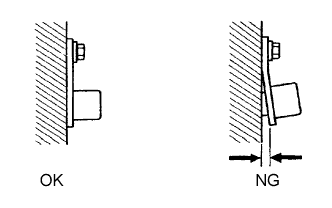
- OK:
- The installation bolt is tightened properly and there is no clearance between the sensor and transmission case.
|
|
||||

| OK | |
 |
| 2. INSPECT SPEED SENSOR (SP2) |
Disconnect the speed sensor (SP2) connector from the transmission.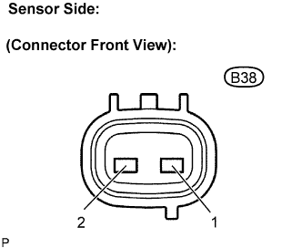
Measure the resistance.
- Standard resistance:
Tester Connection
Specified Condition
1 - 2
560 to 680 Ω at 20°C (68°F)
|
|
||||
| OK | |
|
| 3. CHECK HARNESS AND CONNECTOR (SPEED SENSOR (SP2) - ECM) |
Connect the speed sensor connector.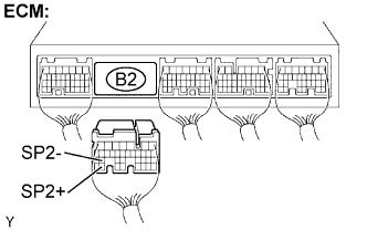
Disconnect the ECM connector.
Measure the resistance.
- Standard resistance:
Tester Connection
Specified Condition
B2-34 (SP2+) - B2-26 (SP2-)
560 to 680 Ω at 20°C (68°F)
Measure the resistance.
- Standard resistance (Check for short):
Tester Connection
Specified Condition
B2-34 (SP2+) - Body ground
10 kΩ or higher
B2-26 (SP2-) - Body ground
10 kΩ or higher
|
|
||||
| OK | ||
 |
||
| ||