B2780 Push Switch / Key Unlock Warning Switch Malfunction
Diagnostic trouble codes · Vehicles built Aug 2009 – Oct 2010
Versions by build date: Jul 2007 – Jul 2009 Aug 2009 – Oct 2010 from Nov 2010
DESCRIPTION
This DTC will be output if the transponder key ECU does not detect that the unlock warning switch is ON even when the ignition switch is in the ON position. Under normal conditions, the unlock warning switch is ON when the ignition switch is in the ON position.| DTC No. |
DTC Detection Condition |
Trouble Area |
| B2780 |
"Unlock warning switch ON" is not detected when ignition switch is ON |
|
WIRING DIAGRAM
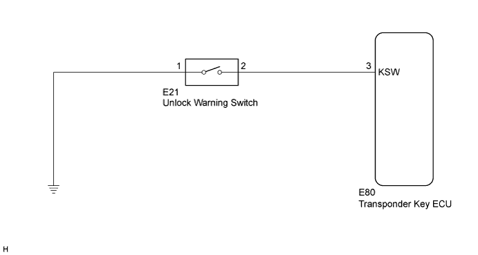

INSPECTION PROCEDURE
- NOTICE:
- If the transponder key ECU is replaced, register the key and ECU communication ID.
| 1. READ VALUE USING INTELLIGENT TESTER |

Connect a intelligent tester to the DLC3.
Turn the ignition switch to ON.
Turn the tester ON.
Enter the following menus: Body Electrical / Immobiliser / Data List.
According to the display on tester, read the "Data List".
| Tester Display |
Measurement Item/Range |
Normal Condition |
Diagnostic Note |
| Key SW |
Unlock warning switch signal/ON or OFF |
ON: Key is in ignition key cylinder OFF: No key is in ignition key cylinder |
- |
- OK:
- ON (Key is in ignition key cylinder) appears on the screen.
|
|
||||

| OK | ||
 |
||
| ||
| 2. INSPECT UNLOCK WARNING SWITCH |
Remove the unlock warning switch (Click here).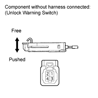
Measure the resistance according to the value(s) in the table below.
- Standard resistance:
Tester Connection
Switch Position
Specified Condition
1 - 2
Switch pushed
(Key set)
Below 1 Ω
Switch free
(Key removed)
10 kΩ or higher
Reinstall the unlock warning switch.
|
|
||||

| OK | |
 |
| 3. CHECK HARNESS AND CONNECTOR (UNLOCK WARNING SWITCH - BODY GROUND) |
Disconnect the E21 unlock warning switch connector.
Measure the resistance according to the value(s) in the table below.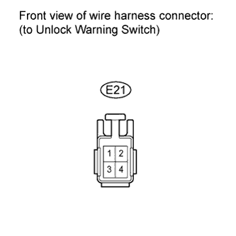
- Standard resistance:
Tester Connection
Condition
Specified Condition
E21-2 - Body ground
Always
Below 1 Ω
Reconnect the unlock warning switch connector.
|
|
||||
| OK | |
|
| 4. CHECK HARNESS AND CONNECTOR (TRANSPONDER KEY ECU - UNLOCK WARNING SWITCH) |
Disconnect the E80 transponder key ECU connector.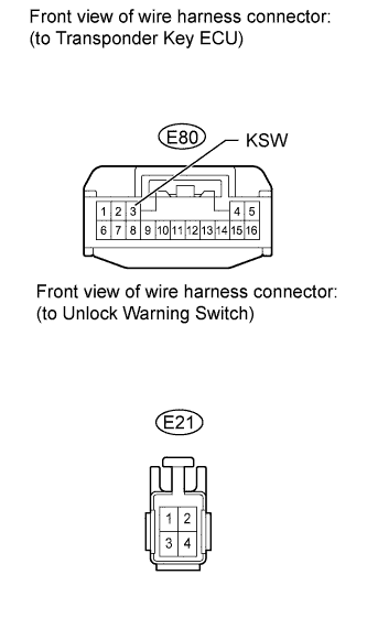
Disconnect the unlock warning switch connector.
Measure the resistance according to the value(s) in the table below.
- Standard resistance:
Tester Connection
Condition
Specified Condition
E80-3 (KSW) - E21-1
Always
Below 1 Ω
E21-1 - Body ground
Always
10 kΩ or higher
Reconnect the transponder key ECU connector.
Reconnect the unlock warning switch connector.
|
|
||||
| OK | ||
|
||
| ||