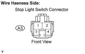
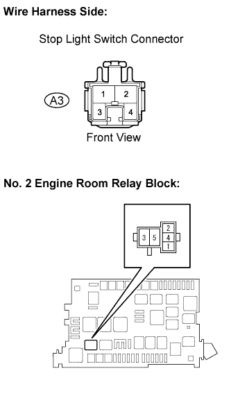
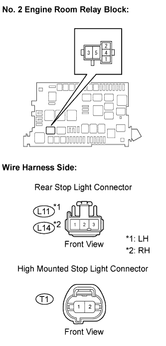
Stop Light Switch Circuit
Circuit diagnosis · Vehicles built Jul 2007 – Oct 2010
Versions by build date: Jul 2007 – Oct 2010 from Nov 2010
DESCRIPTION
When the stop light switch is turned on, the current flows to the stop lights to illuminate.WIRING DIAGRAM
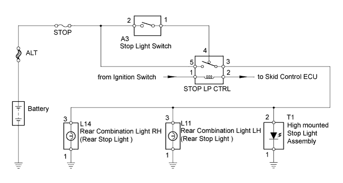

INSPECTION PROCEDURE
| 1. INSPECT FUSE (STOP) |
 |
Remove the STOP fuse from the No. 2 engine room relay block.
Measure the resistance according value(s) in the table below.
- Standard resistance:
Tester Connection
|
Condition
|
Specified Condition
|
STOP fuse
|
Always
|
Below 1 Ω
|
Reinstall the STOP fuse.
|
NG |
 |
|
|
|
| OK |
|
 |
|
| 2. INSPECT BULB (REAR STOP LIGHT BULB) |
|
Remove the rear stop light bulbs.
Remove the high mounted stop light assembly.
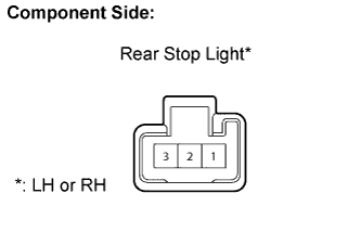
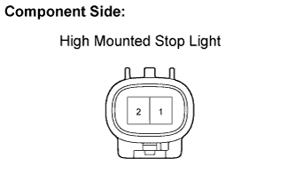
Apply battery voltage to the terminals and check that the rear stop light and high mounted stop light illuminates.
- OK:
Rear stop light
Measurement Condition
|
Specified Condition
|
Positive battery - Terminal 3
Negative battery - Terminal 1
|
Stop light bulb illuminates
|
High mounted stop light
Measurement Condition
|
Specified Condition
|
Positive battery - Terminal 2
Negative battery - Terminal 1
|
High mounted stop light illuminates
|
Reinstall the rear stop light bulbs.
Reinstall the high mounted stop light assembly.
- Result:
Result
|
Proceed to
|
OK
|
A
|
NG (Rear stop light)
|
B
|
NG (High mounted stop light)
|
C
|
|
B |
|
|
|
|
|
C |
|
|
| REPLACE HIGH MOUNTED STOP LIGHT ASSEMBLY (Click here)
|
|
|
| A |
|
|
|
| 3. INSPECT STOP LIGHT SWITCH |
|
- Remove the stop light switch.
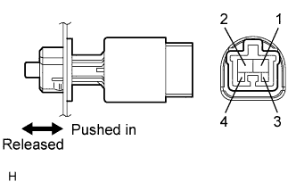
Measure the resistance according value(s) in the table below..
- Standard resistance:
Tester Connection
|
Condition
|
Specified Condition
|
1 - 2
|
Switch pin released
|
Below 1 Ω
|
3 - 4
|
Switch pin pushed in
|
10 kΩ or higher
|
1 - 2
|
Switch pin pushed in
|
10 kΩ or higher
|
3 - 4
|
Switch pin released
|
Below 1 Ω
|
Reinstall the stop light switch.
|
NG |
|
|
|
|
| OK |
|
|
|
| 4. INSPECT STOP LP CTRL RELAY |
|
- Remove the STOP LP CTRL relay from the No. 2 engine room relay block.
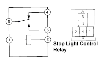
Measure the resistance according value(s) in the table below.
- Standard resistance:
Tester Connection
|
Condition
|
Specified Condition
|
3 - 4
|
Voltage is not applied between terminals 1 and 2
|
Below 1 Ω
|
3 - 5
|
Voltage is not applied between terminals 1 and 2
|
10 kΩ or higher
|
3 - 4
|
Apply the battery voltage between terminals 1 and 2
|
10 kΩ or higher
|
3 - 5
|
Apply the battery voltage between terminals 1 and 2
|
Below 1 Ω
|
Reinstall the STOP LP CTRL relay.
|
NG |
|
|
| REPLACE STOP LP CTRL RELAY |
|
|
| OK |
|
|
|
| 5. CHECK HARNESS AND CONNECTOR (FUSE - STOP LIGHT SWITCH) |
|
- Disconnect the A3 stop light switch connector.
Measure the voltage according value(s) in the table below.
- Standard voltage:
Tester Connection
|
Condition
|
Specified Condition
|
A3-2 - Body ground
|
Always
|
11 to 14 V
|
Reconnect the stop light switch connector.
|
NG |
|
|
| REPAIR OR REPLACE HARNESS OR CONNECTOR |
|
|
| OK |
|
|
|
| 6. CHECK HARNESS AND CONNECTOR (STOP LIGHT SWITCH - STOP LIGHT CONTROL RELAY) |
|
- Disconnect the A3 stop light switch connector.
Remove the STOP LP CTRL relay from the No. 2 engine room relay block.
Measure the resistance according value(s) in the table below.
- Standard resistance:
Tester Connection
|
Condition
|
Specified Condition
|
A3-1 - STOP LP CTRL relay terminal 4
|
Always
|
Below 1 Ω
|
A3-1 or STOP LP CTRL relay terminal 4 - Body ground
|
Always
|
10 kΩ or higher
|
Reconnect the stop light switch connector.
Reinstall the STOP LP CTRL relay.
|
NG |
|
|
| REPAIR OR REPLACE HARNESS OR CONNECTOR |
|
|
| OK |
|
|
|
| 7. CHECK HARNESS AND CONNECTOR (STOP LIGHT CONTROL RELAY - REAR STOP LIGHT) |
|
- Remove the STOP LP CTRL relay from the No. 2 engine room relay block.
Disconnect the L11 and L14 rear stop light connectors.
Disconnect the T1 high mounted stop light connector.
Measure the resistance according value(s) in the table below.
- Standard resistance:
Tester Connection
|
Condition
|
Specified Condition
|
STOP LP CTRL relay terminal 3 - L11-3
|
Always
|
Below 1 Ω
|
STOP LP CTRL relay terminal 3 - L14-3
|
Always
|
Below 1 Ω
|
STOP LP CTRL relay terminal 3 - T1-2
|
Always
|
Below 1 Ω
|
STOP LP CTRL relay terminal 3 - Body ground
|
Always
|
10 kΩ or higher
|
Reinstall the STOP LP CTRL relay.
Reconnect the stop light connectors.
Reconnect the high mounted stop light connector.
|
NG |
|
|
| REPAIR OR REPLACE HARNESS OR CONNECTOR |
|
|
| OK |
|
 |
|
| REPAIR OR REPLACE HARNESS OR CONNECTOR (REAR STOP LIGHT - BODY GROUND) |
|