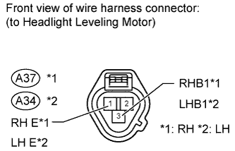
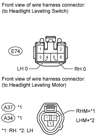
Circuit diagnosis · Vehicles built Jul 2007 – Oct 2010
Versions by build date: Jul 2007 – Oct 2010from Nov 2010
DESCRIPTION
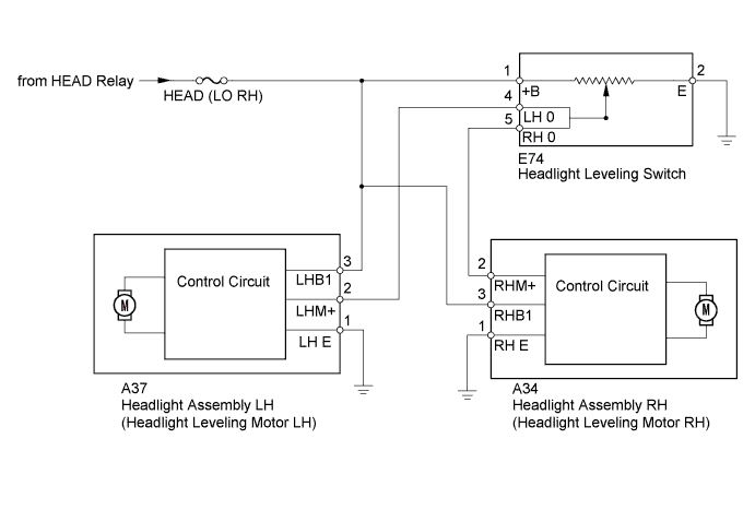
The headlight leveling motors are activated by operating the headlight leveling switch, allowing the headlight beam angle to be adjusted.
WIRING DIAGRAM
INSPECTION PROCEDURE
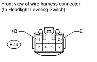
1. INSPECT HEADLIGHT LEVELING SWITCH
Remove the headlight leveling switch.
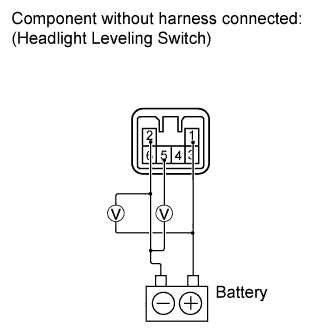
RH circuit:
Connect the positive (+) battery lead to terminal 1 and the negative (-) battery lead to terminal 2.
Check the ratio which is obtained by dividing the voltage between terminals 5 and 2 by the voltage between 1 and 2. The voltages must be measured using a voltmeter.
Standard Ratio:
Tester Connection
Switch Condition
Specified Condition
1 (+B) - 2 (E) and 5 (RH 0) - 2 (E)
0
0.87 to 0.93
1
0.71 to 0.77
2
0.55 to 0.61
3
0.39 to 0.45
4
0.23 to 0.29
5
0.07 to 0.13
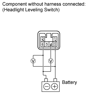
LH circuit:
Connect the positive (+) battery lead to terminal 1 and the negative (-) battery lead to terminal 2.
Check the ratio which is obtained by dividing the voltage between terminals 4 and 2 by the voltage between 1 and 2. The voltages must be measured using a voltmeter.