Taillight Relay Circuit
Circuit diagnosis · Vehicles built from Nov 2010
Versions by build date: Jul 2007 – Oct 2010 from Nov 2010
DESCRIPTION
The headlight dimmer switch sends a signal to the main body ECU.WIRING DIAGRAM
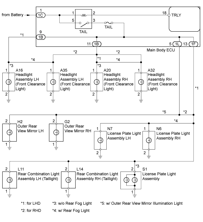

INSPECTION PROCEDURE
- NOTICE:
- Inspect the fuses and bulbs for circuits related to this system before performing the following inspection procedure.
| 1. PERFORM ACTIVE TEST USING INTELLIGENT TESTER (TAIL LIGHT) |

Connect the intelligent tester to the DLC3.
Turn the ignition switch to ON.
Turn the tester on.
Enter the following menus: Body / Main Body / Active Test / Tail Light
According to the display on the tester, perform the Active Test.
Main Body Tester Display
Test Part
Control Range
Normal Condition
Tail Light
Taillight Relay
ON/OFF
-
- OK:
- Taillight relay operates. (Taillights Illuminate.)
|
|
||||

| OK | ||
 |
||
| ||
| 2. SYSTEM CHECK |
Select the condition that best describes the results of the previous step 1.
*1: w/ Outer rear view Mirror Illumination LightResult Result
Proceed to
No illumination lights illuminate
A
Front clearance light does not illuminate
B
License plate does not illuminate
C
Taillight does not illuminate
D
Outer rear view mirror illumination light does not illuminate*1
E
|
|
||||
|
|
||||
|
|
||||
|
|
||||
| A | |
 |
| 3. INSPECT TAIL RELAY |
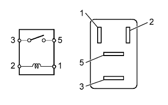 |
Remove the TAIL relay from the main body ECU (Click here).
Measure the resistance according to the value(s) in the table below.
- Standard Resistance:
Tester Connection
Condition
Specified Condition
3 - 5
Battery voltage not applied
10 kΩ or higher
Battery voltage applied to terminals 1 and 2
Below 1 Ω
Reinstall the TAIL relay.
|
|
||||

| OK | |
|
| 4. CHECK HARNESS AND CONNECTOR (MAIN BODY ECU - BATTERY) |
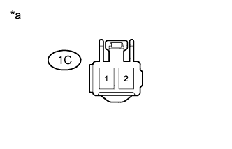 |
Disconnect the 1C main body ECU connector.
Measure the voltage according to the value(s) in the table below.
- Standard Voltage:
Tester Connection
Condition
Specified Condition
1C-1 - Body ground
Always
11 to 14 V
Text in Illustration *a
Front view of wire harness connector
(to Main Body ECU)
Reconnect the main body ECU connector.
|
|
||||
| OK | ||
|
||
| ||
| 5. CHECK HARNESS AND CONNECTOR (HEADLIGHT ASSEMBLY - MAIN BODY ECU AND BODY GROUND) |
for LHD without Rear Fog Light
Disconnect the A16 and A20 headlight assembly connectors.
Disconnect the 1B main body ECU connector.
Measure the resistance according to the value(s) in the table below.
- Standard Resistance:
Tester Connection
Condition
Specified Condition
A16-1 - 1B-9
Always
Below 1 Ω
A16-1 - Body ground
Always
10 kΩ or higher
A16-2 - Body ground
Always
Below 1 Ω
A20-1 - 1B-11
Always
Below 1 Ω
A20-1 - Body ground
Always
10 kΩ or higher
A20-2 - Body ground
Always
Below 1 Ω
Reconnect the main body ECU connector.
Reconnect the headlight assembly connectors.
for LHD with Rear Fog Light
Disconnect the A32 and A35 headlight assembly connectors.
Disconnect the 1B main body ECU connector.
Measure the resistance according to the value(s) in the table below.
- Standard Resistance:
Tester Connection
Condition
Specified Condition
A35-1 - 1B-9
Always
Below 1 Ω
A35-1 - Body ground
Always
10 kΩ or higher
A35-2 - Body ground
Always
Below 1 Ω
A32-1 - 1B-11
Always
Below 1 Ω
A32-1 - Body ground
Always
10 kΩ or higher
A32-2 - Body ground
Always
Below 1 Ω
Reconnect the main body ECU connector.
Reconnect the headlight assembly connectors.
for RHD
Disconnect the A32 and A35 headlight assembly connectors.
Disconnect the 1B main body ECU connector.
Measure the resistance according to the value(s) in the table below.
- Standard Resistance:
Tester Connection
Condition
Specified Condition
A35-1 - 1B-11
Always
Below 1 Ω
A35-1 - Body ground
Always
10 kΩ or higher
A35-2 - Body ground
Always
Below 1 Ω
A32-1 - 1B-11
Always
Below 1 Ω
A32-1 - Body ground
Always
10 kΩ or higher
A32-2 - Body ground
Always
Below 1 Ω
Reconnect the main body ECU connector.
Reconnect the headlight assembly connectors.
Result Result
Proceed to
NG
A
OK (w/o Headlight Leveling)
B
OK (w/ Headlight Leveling)
C
|
|
||||
|
|
||||
| A | ||
|
||
| ||
| 6. CHECK HARNESS AND CONNECTOR (LICENSE PLATE LIGHT ASSEMBLY - MAIN BODY ECU AND BODY GROUND) |
for LHD without Rear Fog Light
Disconnect the S1 license plate light assembly connector.
Disconnect the 1F main body ECU connector.
Measure the resistance according to the value(s) in the table below.
- Standard Resistance:
Tester Connection
Condition
Specified Condition
S1-2 - 1F-13
Always
Below 1 Ω
S1-2 - Body ground
Always
10 kΩ or higher
S1-1 - Body ground
Always
Below 1 Ω
Reconnect the main body ECU connector.
Reconnect the license plate light assembly connector.
for LHD with Rear Fog Light
Disconnect the N6 and N7 license plate light assembly connectors.
Disconnect the 1F main body ECU connector.
Measure the resistance according to the value(s) in the table below.
- Standard Resistance:
Tester Connection
Condition
Specified Condition
N7-1 - 1F-13
Always
Below 1 Ω
N7-1 - Body ground
Always
10 kΩ or higher
N7-2 - Body ground
Always
Below 1 Ω
N6-1 - 1F-13
Always
Below 1 Ω
N6-1 - Body ground
Always
10 kΩ or higher
N6-2 - Body ground
Always
Below 1 Ω
Reconnect the main body ECU connector.
Reconnect the license plate light assembly connectors.
for RHD
Disconnect the N6 and N7 license plate light assembly connectors.
Disconnect the 1L main body ECU connector.
Measure the resistance according to the value(s) in the table below.
- Standard Resistance:
Tester Connection
Condition
Specified Condition
N7-1 - 1L-5
Always
Below 1 Ω
N7-1 - Body ground
Always
10 kΩ or higher
N7-2 - Body ground
Always
Below 1 Ω
N6-1 - 1L-5
Always
Below 1 Ω
N6-1 - Body ground
Always
10 kΩ or higher
N6-2 - Body ground
Always
Below 1 Ω
Reconnect the main body ECU connector.
Reconnect the license plate light assembly connectors.
Result Result
Proceed to
NG
A
OK (w/o Rear Fog Light)
B
OK (w/ Rear Fog Light)
C
|
|
||||
|
|
||||
| A | ||
|
||
| ||
| 7. CHECK HARNESS AND CONNECTOR (REAR COMBINATION LIGHT ASSEMBLY - MAIN BODY ECU AND BODY GROUND) |
for LHD
Disconnect the L11 and L14 rear combination light assembly connectors.
Disconnect the 1F main body ECU connector.
Measure the resistance according to the value(s) in the table below.
- Standard Resistance:
Tester Connection
Condition
Specified Condition
L11-2 - 1F-13
Always
Below 1 Ω
L11-2 - Body ground
Always
10 kΩ or higher
L11-1 - Body ground
Always
Below 1 Ω
L14-2 - 1F-13
Always
Below 1 Ω
L14-2 - Body ground
Always
10 kΩ or higher
L14-1 - Body ground
Always
Below 1 Ω
Reconnect the main body ECU connector.
Reconnect the rear combination light assembly connectors.
for RHD
Disconnect the L11 and L14 rear combination light assembly connectors.
Disconnect the 1L main body ECU connector.
Measure the resistance according to the value(s) in the table below.
- Standard Resistance:
Tester Connection
Condition
Specified Condition
L11-2 - 1L-5
Always
Below 1 Ω
L11-2 - Body ground
Always
10 kΩ or higher
L11-1 - Body ground
Always
Below 1 Ω
L14-2 - 1L-5
Always
Below 1 Ω
L14-2 - Body ground
Always
10 kΩ or higher
L14-1 - Body ground
Always
Below 1 Ω
Reconnect the main body ECU connector.
Reconnect the rear combination light assembly connectors.
Result Result
Proceed to
NG
A
OK (w/o Rear Fog Light)
B
OK (w/ Rear Fog Light)
C
|
|
||||
|
|
||||
| A | ||
|
||
| ||
| 8. CHECK HARNESS AND CONNECTOR (OUTER REAR VIEW MIRROR - MAIN BODY ECU AND BODY GROUND) |
Disconnect the H2 and G2 outer rear view mirror connectors.
Disconnect the 1L main body ECU connector.
Measure the resistance according to the value(s) in the table below.
- Standard Resistance:
Tester Connection
Condition
Specified Condition
H2-2 - 1L-5
Always
Below 1 Ω
H2-2 - Body ground
Always
10 kΩ or higher
H2-1 - Body ground
Always
Below 1 Ω
G2-2 - 1L-5
Always
Below 1 Ω
G2-2 - Body ground
Always
10 kΩ or higher
G2-1 - Body ground
Always
Below 1 Ω
Reconnect the main body ECU connector.
Reconnect the outer rear view mirror connectors.
|
|
||||
| OK | ||
|
||
| ||