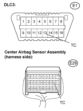
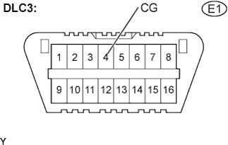
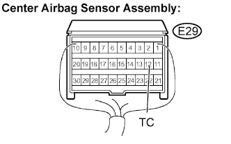
TC and CG Terminal Circuit
Circuit diagnosis · Vehicles built Jul 2007 – Jul 2011
Versions by build date: Jul 2007 – Jul 2011 Aug 2011 – Jul 2012 from Aug 2012
DESCRIPTION
DTC output mode is set by connecting terminals TC and CG of the DLC3.The stored DTCs are indicated by the blinking patterns of the SRS warning light.WIRING DIAGRAM
- HINT:
- When all the warning lights continue blinking, a ground short in the wiring of terminal TC of the DLC3 is suspected.
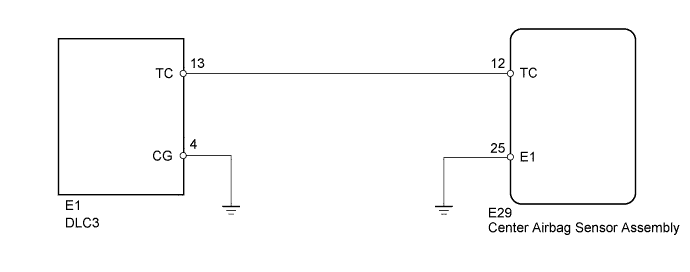

INSPECTION PROCEDURE
| 1. CHECK HARNESS AND CONNECTOR (DLC3 - CENTER AIRBAG SENSOR ASSEMBLY) |
 |
Turn the ignition switch off.
Disconnect the negative (-) terminal cable from the battery, and wait for at least 90 seconds.
- Disconnect the connector from the center airbag sensor assembly.
Measure the resistance.
- Standard resistance:
Tester Connection
|
Specified Condition
|
TC (E29-12) - TC (E1-13)
|
Below 1 Ω
|
Reconnect the connector.
|
NG |
 |
|
| REPAIR OR REPLACE HARNESS OR CONNECTOR |
|
|
| OK |
|
 |
|
| 2. CHECK HARNESS AND CONNECTOR (DLC3 - BODY GROUND) |
|
- Measure the resistance.
- Standard resistance:
Tester Connection
|
Specified Condition
|
CG (E1-4) - Body ground
|
Below 1 Ω
|
|
NG |
|
|
| REPAIR OR REPLACE HARNESS OR CONNECTOR |
|
|
| OK |
|
|
|
| 3. CHECK HARNESS AND CONNECTOR (CENTER AIRBAG SENSOR ASSEMBLY - BODY GROUND) |
|
- Measure the resistance.
- Standard resistance:
Tester Connection
|
Specified Condition
|
TC (E29-12) - Body ground
|
10 kΩ or higher
|
|
NG |
|
|
| REPAIR OR REPLACE HARNESS OR CONNECTOR |
|
|
| OK |
|
 |
|
| REPLACE CENTER AIRBAG SENSOR ASSEMBLY (Click here)
|
|