REMOVAL
Removal / installation · Vehicles built from Jul 2007
- HINT:
- The procedure described below is for the LH side. Use the same procedure for both the RH and LH sides, unless otherwise specified.
| 1. REMOVE ACCESS PANEL REAR WEATHERSTRIP |

- HINT:
- Use the same procedure as for the RH side (Click here).
| 2. REMOVE LAP BELT OUTER ANCHOR COVER |
- HINT:
- Use the same procedure as for the RH side (Click here).
| 3. REMOVE ACCESS DOOR INSIDE HANDLE SUB-ASSEMBLY |
- HINT:
- Use the same procedure as for the RH side (Click here).
| 4. REMOVE CUP HOLDER |
- HINT:
- Use the same procedure as for the RH side (Click here).
| 5. REMOVE ACCESS DOOR TRIM BOARD SUB-ASSEMBLY |
- HINT:
- Use the same procedure as for the RH side (Click here).
| 6. REMOVE CENTER PILLAR UPPER GARNISH |
- HINT:
- Use the same procedure as for the RH side (Click here).
| 7. REMOVE ACCESS DOOR OPENING TRIM |
- HINT:
- Use the same procedure as for the RH side (Click here).
| 8. REMOVE ACCESS PANEL WEATHERSTRIP |
- HINT:
- Use the same procedure as for the RH side (Click here).
| 9. REMOVE ACCESS DOOR GLASS OUTER WEATHERSTRIP |
Apply protective tape to the rear door panel in the area around the access door glass outer weatherstrip.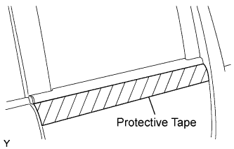

Using a moulding remover, disengage the 3 clips and remove the access door glass outer weatherstrip.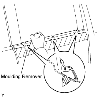
| 10. REMOVE ACCESS DOOR GLASS SUB-ASSEMBLY |
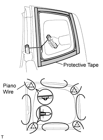 |
Apply protective tape to the outer circumference of the rear door glass, as shown in the illustration.
From the interior, insert piano wires between the vehicle body and rear door glass, as shown in the illustration.
Tie objects that can serve as handles (for example, wooden blocks) to all wire ends.
- NOTICE:
- When separating the rear door glass from the vehicle, do not damage the vehicle's paintwork or exterior/interior ornaments.
Cut through the adhesive by pulling the piano wire around the rear door glass.
| 11. REMOVE NO. 4 BLACK OUT TAPE |
Using an infrared light, heat the No. 4 black out tape.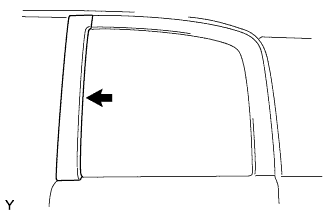
- CAUTION:
- Do not burn yourself with the heated front door panel or infrared light.
- HINT:
- Heat at 40 to 60°C (104 to 140°F) for 3 to 5 minutes.
Lift the end portion with your nail and peel it parallel to the attachment surface.
| 12. REMOVE NO. 6 BLACK OUT TAPE |
Using an infrared light, heat the No. 6 black out tape.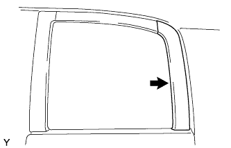
- CAUTION:
- Do not burn yourself with the heated front door panel or infrared light.
- HINT:
- Heat at 40 to 60°C (104 to 140°F) for 3 to 5 minutes.
Lift the end portion with your nail and peel it parallel to the attachment surface.
| 13. REMOVE NO. 5 BLACK OUT TAPE |
Using an infrared light, heat the No. 6 black out tape.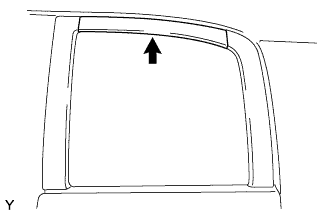
- CAUTION:
- Do not burn yourself with the heated front door panel or infrared light.
- HINT:
- Heat at 40 to 60°C (104 to 140°F) for 3 to 5 minutes.
Lift the end portion with your nail and peel it parallel to the attachment surface.