INSTALLATION
Removal / installation · Vehicles built Jul 2007 – Jul 2009
Versions by build date: Jul 2007 – Jul 2009 from Aug 2009
| 1. INSTALL FUEL SUCTION WITH PUMP AND GAUGE TUBE ASSEMBLY |

Install a new gasket onto the fuel tank.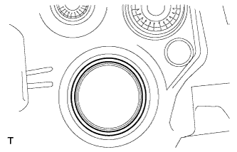

Set the fuel suction tube assembly to the fuel tank.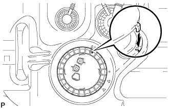
- NOTICE:
- Do not bend the arm of the fuel sender gauge.
Fit the spline of the fuel suction tube assembly into the keyway of the fuel tank.
Install a new retainer.
Align the mark on a new retainer with the rib on the fuel tank as shown in the illustration.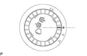
Using SST, turn the retainer 740° to 760° clockwise (more than 2 turns), and position the mark on the retainer within range A to install it.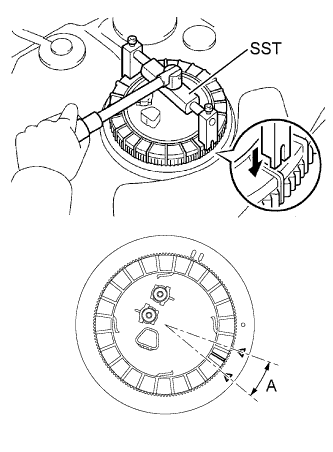
- SST
- 09808-14020
(09808-01410, 09808-01420, 09808-01430)
- HINT:
- Align the tips of the SST with the ribs on the retainer.
| 2. INSTALL FUEL TANK MAIN TUBE AND FUEL TANK RETURN TUBE |
Install the fuel tank main tube and return tube with the 2 joint clips.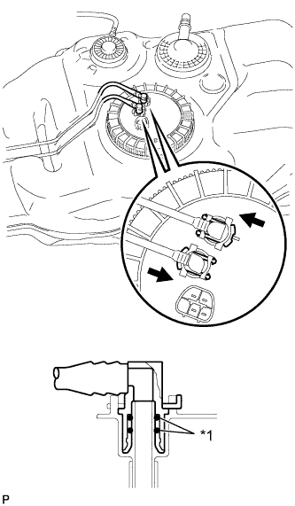
Text in Illustration *1
O-Ring

Push
- NOTICE:
- Check that there are no scratches or foreign matter around the disconnected part of the fuel tube joint and plug before performing this work.
- Check that the fuel tube joint is securely inserted into the end.
- Check that the tube joint clips are on the collar of the fuel tube joint.
- After installing the tube joint clip, check that the fuel tank main tube and return tube can be pulled out.
- Check that there are no scratches or foreign matter around the disconnected part of the fuel tube joint and plug before performing this work.
| 3. INSTALL FUEL TANK ASSEMBLY |
Set a mission jack onto the fuel tank.
Install the fuel tank and 2 fuel tank bands with the 2 clips, 2 pins and the 2 bolts.
- Torque:
- 40 N*m{ 408 kgf*cm , 30 ft.*lbf }
| 4. CONNECT FUEL TANK BREATHER TUBE |
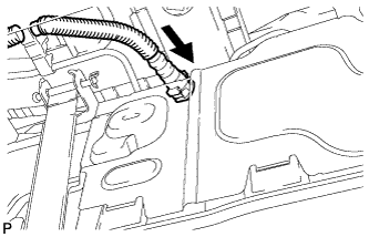 |
|
|
Push |
Connect the fuel tank breather tube.
Align the fuel tank breather tube connector with the pipe, then push in the fuel tank vent connector until the retainer makes a click sound.
- NOTICE:
- Check that there are no scratches or foreign matter on the disconnected parts of the fuel tank vent connector and pipe before performing the work.
- After connecting the fuel tank breather tube, check that the fuel tank breather tube is securely connected by pulling the quick connector.
- Check that there are no scratches or foreign matter on the disconnected parts of the fuel tank vent connector and pipe before performing the work.
| 5. CONNECT FUEL CUT-OFF TUBE |
Push the tube connector into the pipe until the connector makes a click sound.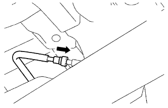
Text in Illustration
Push
- NOTICE:
- Check that there is no damage or foreign objects on the connected part of the pipe.
- After connecting, check that the pipe and the connector are securely connected by pulling them.
- Check that there is no damage or foreign objects on the connected part of the pipe.
| 6. CONNECT FUEL TANK MAIN TUBE AND FUEL TANK RETURN TUBE |
Install the fuel tank main tube and return tube with the 2 joint clips.
Text in Illustration *1
O-Ring
Push
- NOTICE:
- Check that there are no scratches or foreign matter around the disconnected part of the fuel tube joint and plug before performing this work.
- Check that the fuel tube joint is securely inserted into the end.
- Check that the tube joint clips are on the collar of the fuel tube joint.
- After installing the tube joint clip, check that the fuel tank main tube and return tube can be pulled out.
- Check that there are no scratches or foreign matter around the disconnected part of the fuel tube joint and plug before performing this work.
| 7. CONNECT FUEL TANK TO FILLER PIPE HOSE |
Connect the fuel tank to filler pipe hose, as shown in the illustration, with the clamp.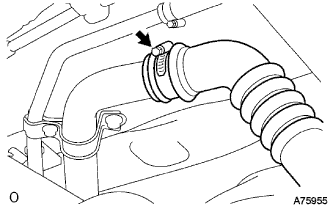
| 8. INSTALL NO.1 FUEL TANK PROTECTOR SUB-ASSEMBLY (for Automatic Transmission) |
Install the fuel tank protector with the 4 nuts.
- Torque:
- 20 N*m{ 204 kgf*cm , 15 ft.*lbf }
Install the fuel tank protector bracket with the 2 nuts.
- Torque:
- 5.5 N*m{ 56 kgf*cm , 49 in.*lbf }
| 9. INSTALL NO.1 FUEL TANK PROTECTOR SUB-ASSEMBLY (for Manual Transmission) |
Install the fuel tank protector with the 4 nuts.
- Torque:
- 20 N*m{ 204 kgf*cm , 15 ft.*lbf }
Install the fuel tank protector bracket with the nut.
- Torque:
- 5.5 N*m{ 56 kgf*cm , 49 in.*lbf }
| 10. INSTALL REAR FLOOR SERVICE HOLE COVER |
Connect the connector.
Install the 3 screws to the center floor.
Install the center floor silencer pad LH.
Install the floor carpet.
| 11. INSTALL REAR SEAT CUSHION ASSEMBLY LH |
Install the rear seat cushion assembly LH with the 2 bolts.
- Torque:
- 37 N*m{ 377 kgf*cm , 27 ft.*lbf }
| 12. INSTALL REAR DOOR SCUFF PLATE LH |
Engage the 6 claws and install the rear door scuff plate.
| 13. INSTALL FRONT DOOR SCUFF PLATE LH |
Engage the 14 claws and install the front door scuff plate.
| 14. INSPECT FOR FUEL LEAK |
Connect the Techstream to the DLC3.
Turn the ignition switch ON.
- NOTICE:
- Do not start the engine.
Turn the Techstream ON.
Select the following menu items: Powertrain / Engine and ECT / Active Test / Activate the Fuel Pump Speed Control / ON.
Check that there is no leakage from the fuel system.