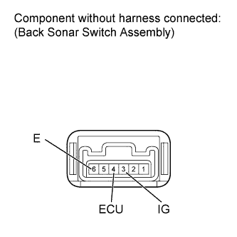
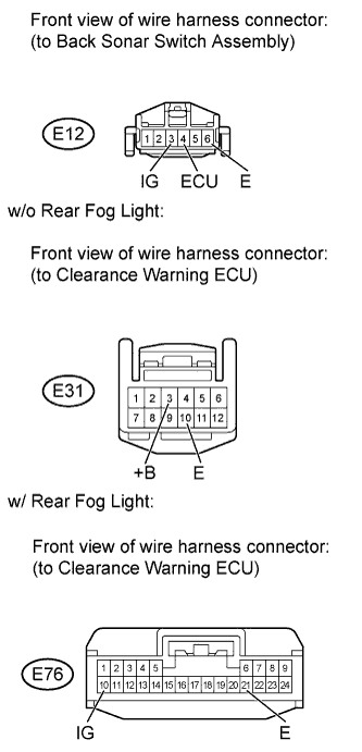
Clearance Sonar Main Switch Circuit
Circuit diagnosis · Vehicles built Jul 2007 – Oct 2010
Versions by build date: Jul 2007 – Oct 2010 from Nov 2010
DESCRIPTION
Turning this switch on activates the Toyota parking assist-sensor system.WIRING DIAGRAM
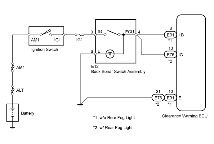

INSPECTION PROCEDURE
| 1. INSPECT BACK SONAR SWITCH ASSEMBLY |
 |
- Remove the back sonar switch assembly.
Measure the resistance according to the value(s) in the table below.
- Standard Resistance:
Tester Connection
|
Switch Condition
|
Specified Condition
|
3 (IG) - 4 (ECU)
|
Back sonar switch ON
|
Below 1 Ω
|
Back sonar switch OFF
|
1 MΩ or higher
|
3 (IG) - 6 (E)
|
Back sonar switch ON
|
Below 30 Ω
|
Back sonar switch OFF
|
10 kΩ or higher
|
Reinstall the back sonar switch assembly.
|
NG |
 |
|
|
|
| OK |
|
 |
|
| 2. CHECK HARNESS AND CONNECTOR (BACK SONAR SWITCH - CLEARANCE WARNING ECU) |
|
- Disconnect the E12 back sonar switch assembly connector.
Disconnect the E31 or E76 clearance warning ECU connector.
Measure the voltage according to the value(s) in the table below.
- Standard Voltage:
Tester Connection
|
Switch Condition
|
Specified Condition
|
E12-3 (IG) - Body ground
|
Ignition switch ON
|
11 to 14 V
|
Measure the resistance according to the value(s) in the table below.
- Standard Resistance:
w/o Rear Fog Light
Tester Connection
|
Condition
|
Specified Condition
|
E12-4 (ECU) - E31-3 (+B)
|
Always
|
Below 1 Ω
|
E12-6 (E) - Body ground
|
E31-10 (E) - Body ground
|
w/ Rear Fog Light
Tester Connection
|
Condition
|
Specified Condition
|
E12-4 (ECU) - E76-10 (IG)
|
Always
|
Below 1 Ω
|
E12-6 (E) - Body ground
|
E76-21 (E) - Body ground
|
Reconnect the back sonar switch connector.
Reconnect the clearance warning ECU connector.
|
NG |
|
|
| REPAIR OR REPLACE HARNESS OR CONNECTOR |
|
|
| OK |
|
|
|
| 3. CHECK CLEARANCE WARNING ECU ASSEMBLY (POWER SOURCE) |
|
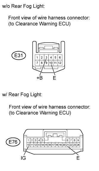
- Disconnect the E31 or E76 clearance warning ECU connector.
Measure the voltage according to the value(s) in the table below.
- Standard Voltage:
w/o Rear Fog Light
Tester Connection
|
Switch Condition
|
Specified Condition
|
E31-3 (+B) - E31-10 (E)
|
Ignition switch ON, back sonar switch ON
|
11 to 14 V
|
w/ Rear Fog Light
Tester Connection
|
Switch Condition
|
Specified Condition
|
E76-10 (IG) - E76-21 (E)
|
Ignition switch ON, back sonar switch ON
|
11 to 14 V
|
Reconnect the clearance warning ECU connector.
|
OK |
|
|
| REPLACE CLEARANCE WARNING ECU ASSEMBLY (Click here)
|
|
|
| NG |
|
 |
|
| PROCEED TO NEXT CIRCUIT INSPECTION SHOWN IN PROBLEM SYMPTOMS TABLE (Click here)
|
|