C1202/58 Brake Fluid Level Low / Open Circuit in Brake Fluid Level Warning Switch Circuit
Diagnostic trouble codes · Vehicles built Jul 2007 – Oct 2010
DESCRIPTION
The brake fluid level warning switch sends the appropriate signal to the skid control ECU when the brake fluid level drops.| DTC No. |
DTC Detecting Conditions |
Trouble Areas |
| C1202/58 |
When any of following conditions detected:
|
|
WIRING DIAGRAM
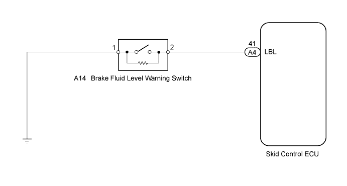

INSPECTION PROCEDURE
- NOTICE:
- When replacing the master cylinder solenoid, perform zero point calibration (Click here).
- HINT:
- When C1241/41 and/or C1242/42 is output together with C1202/58, inspect and repair the trouble areas indicated by C1241/41 and/or C1242/42 first.
| 1. CHECK BRAKE FLUID LEVEL |

Turn the ignition switch off.
Depress the brake pedal 20 times or more (until the pedal reaction feels light and pedal stroke becomes longer).
- HINT:
- When the ignition switch is turned to ON, brake fluid is sent to the accumulator and the fluid level decreases by approximately 5 mm from the level when the ignition switch is OFF (normal).
- NOTICE:
- Do not move the wheels with the ignition switch off.
- OK:
- Brake fluid level is correct.
|
|
||||

| OK | |
 |
| 2. INSPECT BRAKE FLUID LEVEL WARNING SWITCH |
Disconnect the brake fluid level warning switch connector.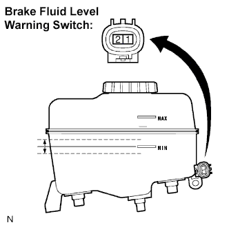
Measure the resistance.
- Standard resistance:
Tester Connection
Condition
Specified Condition
1 - 2
Float UP (Switch OFF)
1.9 k to 2.1 kΩ
1 - 2
Float DOWN (Switch ON)
Below 1 Ω
- NOTICE:
- If there is no problem after finishing the above check, adjust the brake fluid level to the maximum level.
|
|
||||
| OK | |
|
| 3. CHECK HARNESS AND CONNECTOR (BRAKE FLUID LEVEL WARNING SWITCH - SKID CONTROL ECU) |
Disconnect the skid control ECU connector.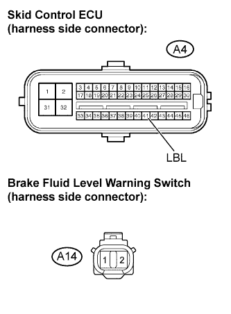
Disconnect the brake fluid level warning switch connector.
Measure the resistance.
- Standard resistance:
Tester Connection
Specified Condition
A4-41 (LBL) - A14-2
Below 1 Ω
A4-41 (LBL) - Body ground
1.9 k to 2.1 kΩ
|
|
||||
| OK | |
|
| 4. RECONFIRM DTC |
Clear the DTC (Click here).
Check if the same DTC is output (Click here).
- Result:
Result
Proceed to
DTC output
A
DTC not output
B
|
|
||||
| A | ||
 |
||
| ||