TERMINALS OF ECM
System information · Vehicles built Aug 2009 – Oct 2010
Versions by build date: Jul 2007 – Jul 2009 Aug 2009 – Oct 2010 from Nov 2010
| CHECK ECM |
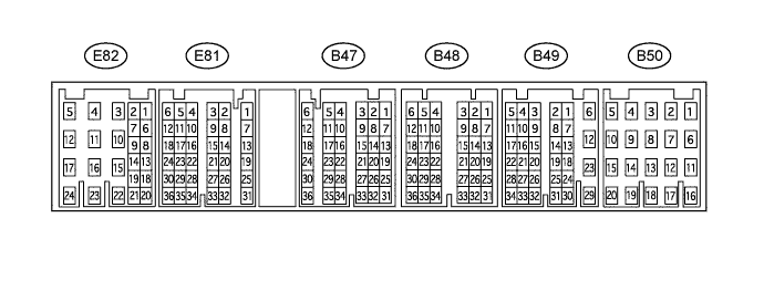

| Terminals No. (Symbols) |
Wiring Color |
Terminal Description |
Condition |
Specified Condition |
| E81-28 (TC) - B49-12 (E1) |
P-L - BR |
DTC output signal |
Ignition switch ON |
11 to 14 V |
| Ignition switch ON Connect terminals TC and CG of DLC3 |
Below 2 V |
|||
| E82-8 (ST1-) - B49-12 (E1) |
R-L - BR |
Cruise cancel input signal |
Ignition switch ON Depress brake pedal |
Below 1 V |
| Ignition switch ON Release brake pedal |
11 to 14 V |
|||
| E81-18 (STP) - B49-12 (E1) |
G-Y - BR |
Stop light switch input signal |
Ignition switch ON Depress brake pedal |
11 to 14 V |
| Ignition switch ON Release brake pedal |
Below 1 V |
|||
| E81-11 (CCS) - B49-12 (E1) |
L-B - BR |
Cruise control main switch output signal |
Ignition switch ON |
11 to 14 V |
| Ignition switch ON CANCEL switch held ON |
6.6 to 10.1 V |
|||
| Ignition switch ON -/SET switch held ON |
4.5 to 7.1 V |
|||
| Ignition switch ON +/RES switch held ON |
2.3 to 4.5 V |
|||
| Ignition switch ON MAIN switch held ON |
Below 1 V |
|||
| E81-15 (PI) - B49-12 (E1) |
P-G - BR |
Cruise main indicator light input signal |
Ignition switch ON Cruise control main switch held ON |
0 to 3 V |
| Ignition switch ON Cruise control main switch held OFF |
11 to 14 V |
|||
| B47-27 (D) - B49-12 (E1)*1 |
L-B - BR |
Clutch switch input signal |
Ignition switch ON Depress clutch pedal |
Below 1 V |
| Ignition switch ON Release clutch pedal |
11 to 14 V |
|||
| B47-27 (D) - B49-12 (E1)*2 |
V - BR |
Clutch switch input signal |
Ignition switch ON and shift lever D or 4 positions |
11 to 14 V |
| Ignition switch ON and shift lever other than D and 4 positions |
Below 1 V |
|||
| B49-12 (E1) - Body ground |
BR - Body ground |
Ground |
Always |
Below 1 V |
- *1: for Manual Transmission
- *2: for Automatic Transmission