INSTALLATION
Removal / installation · Vehicles built from Nov 2010
Versions by build date: Jul 2007 – Jul 2009 Aug 2009 – Oct 2010 from Nov 2010
| 1. INSTALL POWER STEERING LINK ASSEMBLY |

Install the power steering link assembly with the 2 bolts and 2 nuts.
- Torque:
- 120 N*m{ 1224 kgf*cm , 89 ft.*lbf }
- NOTICE:
- Hold the nuts and tighten the bolts to install the power steering link assembly.
| 2. CONNECT PRESSURE FEED TUBE ASSEMBLY (for LHD) |
Install the pressure feed tube clamp with the 2 bolts.
- Torque:
- 28 N*m{ 286 kgf*cm , 21 ft.*lbf }
Using a union nut wrench (17 mm), connect the pressure feed tube assembly (pressure feed tube side) to the power steering link assembly.
- Torque:
- 25 N*m{ 255 kgf*cm , 18 ft.*lbf }
- NOTICE:
- Use the formula to calculate special torque values for situations where a union nut wrench is combined with a torque wrench (Click here).
Connect the pressure feed tube assembly (return tube side) to the power steering link assembly with the clip.
| 3. CONNECT NO. 1 PRESSURE FEED TUBE (for RHD) |
Install the No. 1 pressure feed tube clamp with the bolt.
- Torque:
- 28 N*m{ 286 kgf*cm , 21 ft.*lbf }
Using a union nut wrench (17 mm), connect the No. 1 pressure feed tube to the power steering link assembly.
- Torque:
- 25 N*m{ 255 kgf*cm , 18 ft.*lbf }
- NOTICE:
- Use the formula to calculate special torque values for situations where a union nut wrench is combined with a torque wrench (Click here).
| 4. CONNECT RETURN TUBE SUB-ASSEMBLY (for RHD) |
Connect the return tube sub-assembly to the power steering link assembly with the clip.
| 5. INSTALL TIE ROD END SUB-ASSEMBLY LH |
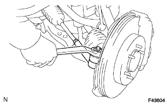  |
Install the tie rod end onto the steering knuckle.
Install the nut.
- Torque:
- 91 N*m{ 928 kgf*cm , 67 ft.*lbf }
Install a new cotter pin.
- NOTICE:
- If the holes in the cotter pin are not aligned, tighten the nut an additional 60°.
| 6. INSTALL TIE ROD END SUB-ASSEMBLY RH |
- HINT:
- Use the same procedure for the RH side as for the LH side.
| 7. INSTALL NO. 2 STEERING INTERMEDIATE SHAFT SUB-ASSEMBLY |
Align the matchmarks on the No. 2 steering intermediate shaft sub-assembly and the power steering link.
Install the No. 2 steering intermediate shaft sub-assembly onto the power steering link with the bolt.
- Torque:
- 36 N*m{ 367 kgf*cm , 27 ft.*lbf }
| 8. INSTALL ENGINE ASSEMBLY |
| 9. INSTALL FRONT WHEELS |
- Torque:
- 112 N*m{ 1137 kgf*cm , 82 ft.*lbf }
| 10. PLACE FRONT WHEELS FACING STRAIGHT AHEAD |
| 11. ADD POWER STEERING FLUID |
| 12. BLEED POWER STEERING FLUID |
Check the fluid level.
Jack up the front of the vehicle and support it with stands.
Turn the steering wheel.
With the engine stopped, turn the wheel slowly from lock to lock several times.
Lower the vehicle.
Start the engine.
Run the engine at idle for a few minutes.
Turn the steering wheel.
With the engine idling, turn the wheel to the left or right full lock position and keep it there for 2 to 3 seconds. Then turn the wheel to the opposite full lock position and keep it there for 2 to 3 seconds (step A).
Repeat step A several times.
Stop the engine.
Check for foaming or emulsification.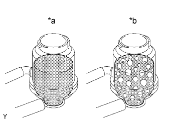
Especially, if the system has to be bled twice because of foaming or emulsification, check for fluid leakage in the system.Text in Illustration *a
Normal
*b
Abnormal
Check the fluid level.
| 13. INSPECT POWER STEERING FLUID LEVEL |
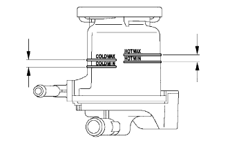 |
Keep the vehicle level.
With the engine stopped, check the fluid level in the oil reservoir.
If necessary, add fluid.- Fluid:
- ATF "DEXRON" II or III
- HINT:
- Check that the fluid level is within the HOT level range in the reservoir tank. If the fluid is cold, check that it is within the COLD level range.
Start the engine and let it idle.
Turn the steering wheel from lock to lock several times to raise fluid temperature.
- Fluid temperature:
- 75 to 80°C (167 to 176°F)
Check for foaming or emulsification.
If any foaming or emulsification is identified, bleed the power steering system.Text in Illustration *a
Normal
*b
Abnormal
With the engine idling, measure the fluid level in the oil reservoir.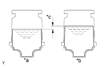
Text in Illustration *a
Engine Idling
*b
Engine Stopped
*c
5 mm (0.20 in.) or less
Stop the engine.
Wait a few minutes and measure the fluid level in the oil reservoir again.
- Maximum fluid level rise:
- 5 mm (0.20 in.)
Check the fluid level.
| 14. INSPECT FOR POWER STEERING FLUID LEAK |
| 15. ADJUST FRONT WHEEL ALIGNMENT |