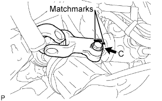
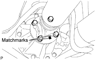
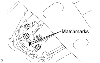
Align the matchmarks on the No. 2 steering intermediate shaft and power steering link.
Install the No. 2 steering intermediate shaft onto the power steering link with bolt C.
Torque:
36 N*m{
367 kgf*cm
, 27 ft.*lbf
}
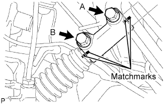
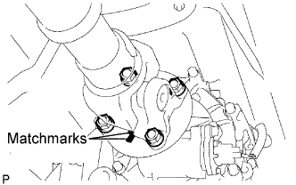
Align the matchmarks on the steering intermediate shaft and steering sliding yoke.
Install the steering sliding yoke onto the steering intermediate shaft and slide it upward.
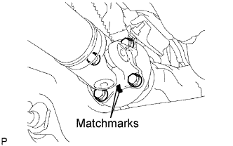
Align the matchmarks on the steering sliding yoke and No. 2 steering intermediate shaft.
Install the steering sliding yoke with bolts A and B.
Torque:
36 N*m{
367 kgf*cm
, 27 ft.*lbf
}
6.
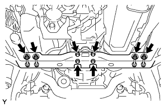
INSTALL NO. 3 FRAME CROSSMEMBER SUB-ASSEMBLY
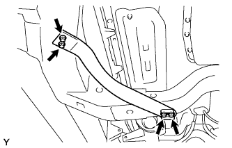
Install the No. 3 frame crossmember sub-assembly with the 4 bolts and 4 nuts.
Torque:
72 N*m{
734 kgf*cm
, 53 ft.*lbf
}
Install the No. 3 frame crossmember sub-assembly with the 4 bolts.
Torque:
30 N*m{
306 kgf*cm
, 22 ft.*lbf
}
7.
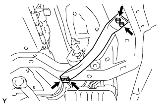
INSTALL FRONT SUSPENSION MEMBER BRACKET LH
Install the front suspension member bracket LH with the 4 bolts.
Torque:
33 N*m{
336 kgf*cm
, 24 ft.*lbf
}
8.
INSTALL FRONT SUSPENSION MEMBER BRACKET RH
Install the front suspension member bracket RH with the 4 bolts.
Torque:
33 N*m{
336 kgf*cm
, 24 ft.*lbf
}
9.
INSTALL PROPELLER SHAFT ASSEMBLY
Align the matchmarks on the propeller shaft flange and differential flange.
Install the propeller shaft assembly with the 4 bolts, 4 nuts and 4 washers.
Torque:
88 N*m{
899 kgf*cm
, 65 ft.*lbf
}
Align the matchmarks on the propeller shaft flange and transfer flange.
Install the propeller shaft assembly with the 4 nuts and 4 washers.
Torque:
88 N*m{
899 kgf*cm
, 65 ft.*lbf
}
10.
INSTALL FRONT PROPELLER SHAFT ASSEMBLY
Align the matchmarks on the yoke and differential flange.
Install the propeller shaft assembly with the 4 bolts, 4 nuts and 4 washers.
Torque:
88 N*m{
899 kgf*cm
, 65 ft.*lbf
}
Align the matchmarks on the yoke and transfer flange.
Install the propeller shaft assembly with the 4 nuts and 4 washers.
Torque:
88 N*m{
899 kgf*cm
, 65 ft.*lbf
}
11.
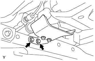
INSTALL PROPELLER SHAFT HEAT INSULATOR
Install the propeller shaft heat insulator with the 2 bolts.
Torque:
16 N*m{
160 kgf*cm
, 12 ft.*lbf
}
12.
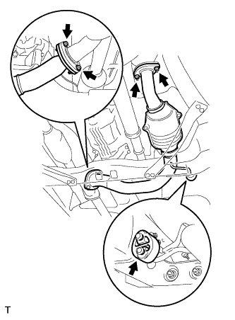
INSTALL FRONT EXHAUST PIPE ASSEMBLY
Install a new gasket onto the exhaust manifold RH.
Install the exhaust front pipe with new 2 nuts.
Torque:
54 N*m{
554 kgf*cm
, 40 ft.*lbf
}
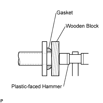
Install a new gasket onto the front exhaust pipe.
Using a wooden block and plastic-faced hammer, tap in a new gasket until it is flush with the front exhaust pipe end.
NOTICE:
Make sure that the gasket is in the correct direction when installing.
Do not reuse the removed gasket.
Do not push in the gasket with the exhaust pipe when connecting it.
13.
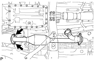
INSTALL NO. 2 EXHAUST FRONT PIPE ASSEMBLY
Install a new gasket onto the exhaust manifold LH.
Install a new gasket onto the No. 2 front exhaust pipe.
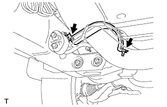
Install the No. 2 front exhaust pipe with 2 new nuts and 2 bolts and exhaust pipe support.
Torque:
Nut:
54 N*m{
554 kgf*cm
, 40 ft.*lbf
}
Bolt:
48 N*m{
489 kgf*cm
, 35 ft.*lbf
}
Install the exhaust pipe stopper bracket with the 2 bolts (for 4WD).
Torque:
19 N*m{
193 kgf*cm
, 14 ft.*lbf
}
14.
INSTALL FRONT WHEELS
Torque:
113 N*m{
1,152 kgf*cm
, 83 ft.*lbf
}
15.
PLACE FRONT WHEELS FACING STRAIGHT AHEAD
16.
INSPECT STEERING WHEEL CENTER POINT
17.
CONNECT CABLE TO NEGATIVE BATTERY TERMINAL
Torque:
3.9 N*m{
40 kgf*cm
, 35 in.*lbf
}
18.
ADD POWER STEERING FLUID
19.
BLEED POWER STEERING FLUID
Check the fluid level.
Jack up the front of the vehicle and support it with stands.
Turn the steering wheel.
With the engine stopped, turn the wheel slowly from lock to lock several times.
Lower the vehicle.
Start the engine.
Run the engine at idle for a few minutes.
Turn the steering wheel.
With the engine idling, turn the wheel to the left or right full lock position and keep it there for 2 to 3 seconds. Then turn the wheel to the opposite full lock position and keep it there for 2 to 3 seconds (step A).
Repeat step A several times.
Stop the engine.
Check for foaming or emulsification. Especially, if the system has to be bled twice because of foaming or emulsification, check for fluid leakage in the system.