REMOVAL
Removal / installation · Vehicles built from Aug 2014
Versions by build date: Aug 2009 – Oct 2010 Nov 2010 – Jul 2014 from Aug 2014
| 1.
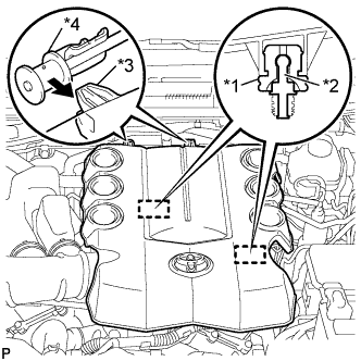
REMOVE V-BANK COVER
|
 |
- Raise the front of the V-bank cover to disengage the 2 cushions of the V-bank cover from the 2 pins.
Text in Illustration
*1
|
Cushion
|
*2
|
Pin
|
*3
|
Hook
|
*4
|
No. 1 V-bank Cover Bracket
|
Disengage the 2 hooks to remove the V-bank cover from the No. 1 V-bank cover bracket.
| 2.
REMOVE AIR CLEANER CAP SUB-ASSEMBLY WITH NO. 1 AIR CLEANER HOSE
|
|
- Raise the front of the V-bank cover to disengage the 2 cushions of the V-bank cover from the 2 pins.
Text in Illustration
*1
|
Cushion
|
*2
|
Pin
|
*3
|
Hook
|
*4
|
No. 1 V-bank Cover Bracket
|
Disengage the 2 hooks to remove the V-bank cover from the No. 1 V-bank cover bracket.
| 3.
REMOVE AIR CLEANER FILTER ELEMENT SUB-ASSEMBLY
|
|
Remove the air cleaner filter element sub-assembly from the air cleaner case sub-assembly.
| 4.
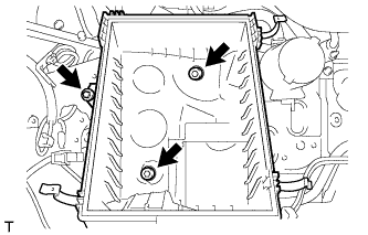
REMOVE AIR CLEANER CASE SUB-ASSEMBLY
|
|
- Remove the 3 bolts and the air cleaner case sub-assembly.
| 5.
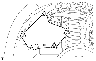
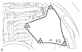
REMOVE FRONT FENDER APRON SEAL LH |
|
- Remove the 5 clips and front fender apron seal LH from the front fender apron sub-assembly LH.
| 6.
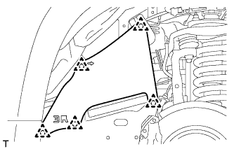
REMOVE FRONT FENDER REAR SPLASH SHIELD LH |
|
- Remove the 5 clips and front fender rear splash shield LH from the front fender apron sub-assembly LH.
| 7.
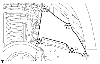
REMOVE FRONT FENDER APRON SEAL RH |
|
- Remove the 4 clips and front fender apron seal RH from the front fender apron sub-assembly RH.
| 8.
REMOVE FRONT FENDER REAR SPLASH SHIELD RH |
|
- Remove the 5 clips and front fender rear splash shield RH from the front fender apron sub-assembly RH.
| 9.
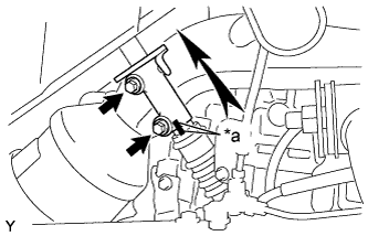
DISCONNECT STEERING SLIDING YOKE (for RHD) |
|
- Put matchmarks on the steering sliding yoke and No. 2 steering intermediate shaft sub-assembly.
Text in Illustration
*a
|
Matchmark
|
Remove the 2 bolts from the steering sliding yoke.
Slide the steering sliding yoke up and separate it from the No. 2 steering intermediate shaft sub-assembly.
| 10.
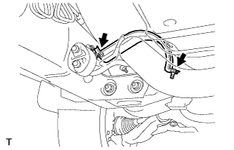
REMOVE EXHAUST PIPE STOPPER BRACKET |
|
- Remove the 2 bolts and exhaust pipe stopper bracket from the frame sub-assembly.
| 11.
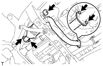
REMOVE FRONT NO. 2 EXHAUST PIPE ASSEMBLY |
|
Disconnect the heated oxygen sensor connector.
- Remove the 2 bolts and disconnect the front No. 2 exhaust pipe assembly from the front exhaust pipe assembly.
Remove the 2 nuts and disconnect the front No. 2 exhaust pipe assembly from the exhaust manifold sub-assembly LH.
Remove the front No. 2 exhaust pipe assembly to the exhaust pipe support.
Remove the 2 gaskets from the front No. 2 exhaust pipe assembly.
| 12.
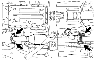
REMOVE FRONT EXHAUST PIPE ASSEMBLY |
|
Disconnect the heated oxygen sensor connector.
- Remove the 2 bolts and 2 compression springs and disconnect the front exhaust pipe assembly from the center exhaust pipe assembly.
Remove the 2 nuts and front exhaust pipe assembly from the exhaust manifold sub-assembly RH.
Remove the 2 gaskets from the front exhaust pipe assembly.
| 13.
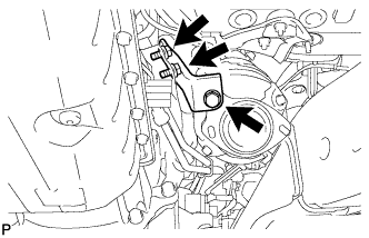
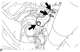
REMOVE MANIFOLD STAY |
|
- Remove the 3 bolts and manifold stay from the exhaust manifold sub-assembly RH.
| 14.
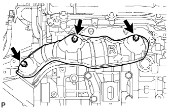
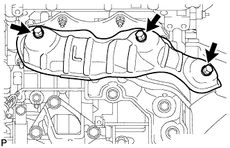
REMOVE NO. 1 EXHAUST MANIFOLD HEAT INSULATOR |
|
- Remove the 3 bolts and No. 1 exhaust manifold heat insulator from the exhaust manifold sub-assembly RH.
| 15.
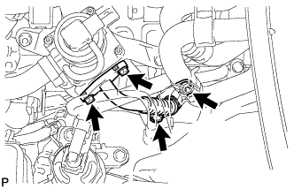
REMOVE AIR TUBE (w/ Secondary Air Injection System)
|
|
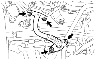
- Remove the 2 bolts, 2 nuts and air tube from the No. 1 emission control valve set and exhaust manifold sub-assembly RH.
Remove the 2 gaskets from the air tube.
- NOTICE:
- Be careful not to damage the installation surface of the gaskets.
| 16.
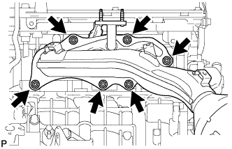
REMOVE EXHAUST MANIFOLD SUB-ASSEMBLY RH (w/ Secondary Air Injection System) |
|
Disconnect the air fuel ratio sensor connector.
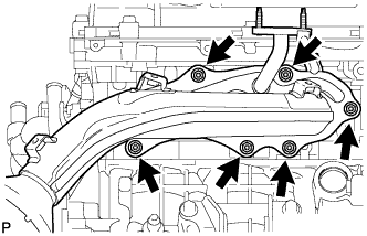
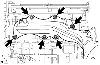
- Remove the 6 nuts and exhaust manifold sub-assembly RH from the cylinder head sub-assembly.
| 17.
REMOVE EXHAUST MANIFOLD SUB-ASSEMBLY RH (w/o Secondary Air Injection System) |
|
Disconnect the air fuel ratio sensor connector.
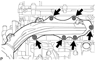
- Remove the 6 nuts and exhaust manifold sub-assembly RH from the cylinder head sub-assembly.
| 18.
REMOVE EXHAUST MANIFOLD TO HEAD GASKET |
|
Remove the exhaust manifold to head gasket from the cylinder head sub-assembly.
| 19.
REMOVE AIR FUEL RATIO SENSOR (for Bank 1 Sensor 1)
|
|
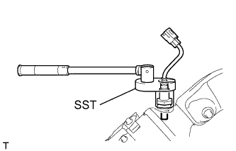
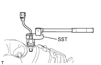
- Using SST, remove the sensor.
- SST
- 09224-00010
| 20.
REMOVE NO. 2 MANIFOLD STAY |
|
- Remove the 3 bolts and No. 2 manifold stay from the exhaust manifold sub-assembly LH.
| 21.
REMOVE NO. 2 EXHAUST MANIFOLD HEAT INSULATOR |
|
- Remove the 3 bolts and No. 2 exhaust manifold heat insulator from the exhaust manifold sub-assembly LH.
| 22.
REMOVE NO. 2 AIR TUBE (w/ Secondary Air Injection System)
|
|
- Remove the 2 bolts, 2 nuts and No. 2 air tube from the No. 2 emission control valve set and exhaust manifold sub-assembly LH.
Remove the 2 gaskets from the No. 2 air tube.
- NOTICE:
- Be careful not to damage the installation surface of the gaskets.
| 23.
REMOVE EXHAUST MANIFOLD SUB-ASSEMBLY LH (w/ Secondary Air Injection System) |
|
Disconnect the air fuel ratio sensor connector.
- Remove the 6 nuts and exhaust manifold sub-assembly LH from the cylinder head sub-assembly.
| 24.
REMOVE EXHAUST MANIFOLD SUB-ASSEMBLY LH (w/o Secondary Air Injection System) |
|
Disconnect the air fuel ratio sensor connector.
- Remove the 6 nuts and exhaust manifold sub-assembly LH from the cylinder head sub-assembly.
| 25.
REMOVE EXHAUST MANIFOLD TO HEAD GASKET LH |
|
Remove the exhaust manifold to head gasket LH from the cylinder head sub-assembly.
| 26.
REMOVE AIR FUEL RATIO SENSOR (for Bank 2 Sensor 1)
|
|
- Using SST, remove the sensor.
- SST
- 09224-00010
| 27.
REMOVE STUD BOLT (w/ Secondary Air Injection System) |
|
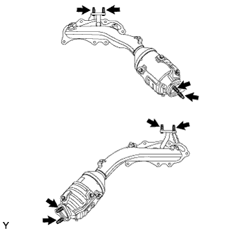
- Using an E6 and E10 "TORX" socket wrench, remove the 8 stud bolts from the exhaust manifold sub-assembly RH and LH.
| 28.
REMOVE STUD BOLT (w/o Secondary Air Injection System) |
|
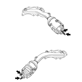
- Using an E10 "TORX" socket wrench, remove the 4 stud bolts from the exhaust manifold sub-assembly RH and LH.